RC-BM5
1-27
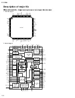
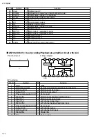
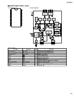
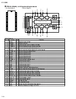
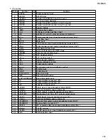
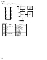
AS4C256KEO (IC701) : DRAM
1. Termianl layout
2. Block diagram
1
2
3
4
5
6
7
8
9
10
11
12
13
14
15
16
17
18
19
20
40
39
38
37
36
35
34
33
32
31
30
29
28
27
26
25
24
23
22
21
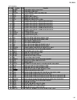
3. Pin function
1
2 to 5
6
7 to 10
11,12
13
14
15
16 to 19
20
21
22 to 26
27
28
29
30
31 to 34
35
36 to 39
40
VCC
I/O0 to I/O3
Vcc
I/O4 to I/O7
NC
WE
RAS
NC
A0 to A3
Vcc
GND
A4 to A8
OE
UCAS
LCAS
NC
I/O8 to I/O11
GND
I/O12 to I/O15
GND
Power (5V 0.5V)
Input/output
Power (5V 0.5V)
Input/output
Not connect
Read/write control
Row address strobe
Not connect
Address inputs
Power (5V 0.5V)
Ground
Address inputs
Output enable
Column address strobe,upper byte
Column address strobe,lower byte
Not connect
Input/output
Ground
Input/output
Ground
Pin No.
Symbol
Function
-
I/O
-
I/O
-
-
-
-
I
-
-
I
O
-
-
-
I/O
-
I/O
-
I/O
CONTROL
LOGIC
CLOCK
GENERATOR
REFRESH
CONTROLER
REFRESH
COUNTER
ROW.
ADDRESS
BUFFERS<9>
DATA-OUT
BUFFER
COLUMN
DECODER
DATA-IN
BUFFER
WE
RAS
CASL
CASH
512
A0
OE
IO0
.
IO15
ROW
DECODER
512
512 x 512 x 16
MEMORY
ARRAY
V
BB
GENERATOR
V
CC
V
SS
512 X 16
SENSE AMPLIFIERS
I/O GATING
A1
A2
A3
A4
A5
A6
A7
A8
COLUMN
ADDRESS
BUFFER
Summary of Contents for RC-BM5
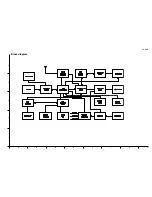
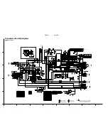
Page 41: ...RC BM5 2 1 A B C D E F G 1 2 3 4 5 Block diagram ...
Page 48: ...RC BM5 2 8 RC BM5 H A B C D E F G 1 2 3 4 5 Printed circuit boards Main board Reverse side ...
Page 49: ...RC BM5 2 9 A B C 1 2 3 4 5 Tuner board Cassette board Reverse side Reverse side ...
Page 50: ...RC BM5 2 10 A B C D 1 2 3 4 5 Display board Reverse side Power amplifier board Reverse side ...
Page 51: ...RC BM5 2 11 A B C 1 2 3 4 5 Volume switch board Reverse side Phone jack board Reverse side ...

