


RC-BM5
1-13
Fig.26
1
2
2
3
3
Fig.28
Arm
af
Arm
ae
CD door
Section
ag
Spring
Cassette mechanism assembly
Rubber (Orange)
CD tray assembly
CD mechanism assembly
W
W
Fig.27
CD door damper
CD door switch
board
Hanger
CD door damper holder
X
Y
(To be loosened)
Z
Claw
ad
Claw
ad
Claws
ac
Spring plate
Rubber (Orange)
Rubber (Pink)
Rubber (Pink)
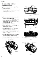
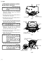
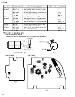
Removing the CD mechanism
assembly
(See Fig. 26.)
From the bottom side of the CD/Cassette
mechanism assembly, remove the screw
X
retaining the CD door switch board.
[Note] When attaching the CD mechanism
assembly, be sure not to mistake the
positions of the pink and orange rubbers.
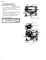
1.
2.
3.
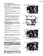
From the bottom side of the CD/Cassette
mechanism assembly, loosen the screw
Y
of the
spring plate holding the hanger and then move the
spring plate in the direction of the arrow
1
.
While pressing the claws
ac
of the hanger in the
direction of the arrow
2
, remove the hanger from
the CD tray assembly.
Press the claws
ad
of the CD open knob in the
direction of the arrow
3
and then take out the CD
open knob from the top side of the CD tray
assembly.
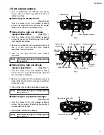
Prior to performing the following procedures,
remove the main board from the CD/Cassette
mechanism assembly.
From the bottom side of the CD/Cassette
mechanism assembly, remove the four screws
W
retaining the CD mechanism assembly.
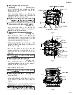
Removing the CD door switch board
(See Fig. 27.)
Removing the hanger and CD door
button
(See Fig. 27.)
[Note]
After assembly, apply a locking agent to
the screw Y.
1.
2.
From the bottom side of the CD/Cassette
mechanism assembly, remove the two screws
Z
retaining the CD door damper holder.
Take out the CD door damper.
Removing the CD door damper
(See Fig. 27.)
[Note]
After assembly, apply a locking agent to
the screws Z.
1.
2.
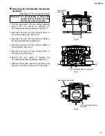
3.
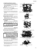
Open the CD door.
While pressing the arm section
ae
of the CD door
in the direction of the arrow, remove the arm
section.
While pressing the arm section
af
of the CD door in
the direction of the arrow, remove the CD door.
Removing the CD door
(See Fig. 28.)
[Note]
When attaching the CD door, hang the
spring to the section ag of the CD door.
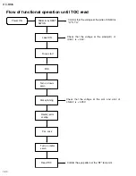
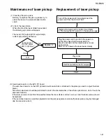
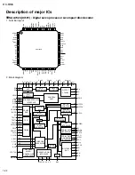
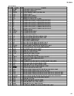
Summary of Contents for RC-BM5
Page 41: ...RC BM5 2 1 A B C D E F G 1 2 3 4 5 Block diagram ...
Page 48: ...RC BM5 2 8 RC BM5 H A B C D E F G 1 2 3 4 5 Printed circuit boards Main board Reverse side ...
Page 49: ...RC BM5 2 9 A B C 1 2 3 4 5 Tuner board Cassette board Reverse side Reverse side ...
Page 50: ...RC BM5 2 10 A B C D 1 2 3 4 5 Display board Reverse side Power amplifier board Reverse side ...
Page 51: ...RC BM5 2 11 A B C 1 2 3 4 5 Volume switch board Reverse side Phone jack board Reverse side ...