PD-42DX
1-10 (No.52088)
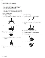
Fig.3
2.4.8 REMOVING THE CHASSIS BASE (Fig.4)
• Remove the REAR COVER.
• Remove the TERMINAL COVER.
• Remove the FILTER SHIELD and LINE FILTER PWB.
• Remove the AUDIO PWB.
• Remove the SYSTEM POWER PWB.
• Remove the DISPLAY INTERFACE PWB.
• Remove the PDP POWER PWB.
(1) Remove the 2 screws [J] and 1 screw [K].
(2) Lift upwards and withdraw the AC inlet in a front direction.
(3) Remove the 4 screws [L], and remove the CHASSIS
BASE.
Fig.4
2.4.9 REMOVING THE PDP UNIT (Fig.5)
• Remove the REAR COVER.
• Remove the TERMINAL COVER.
• Remove the CHASSIS BASE (with each PWB affixed on the
CHASSIS BASE).
(1) Remove the 4 screws [M], and remove the TERMINAL
BRACKET.
(2) Disconnect the connectors of the following PWB.
NOTE:
• Disconnect the connector [CN0PW] from the LINE
FILTER PWB.
• Disconnect the connectors [CN0AU] and [CN0AT]
from the PDP POWER PWB.
• Disconnect the connector [CN0AH] and earth wire
from the DISPLAY INTERFACE PWB.
• It is advisable to take note of the connecting location
(connector number) of the removed connectors.
(3) Remove the 4 screws [N] and 5 screws [O], and remove
the 2 pieces of SUPPORT BRACKET (BOTTOM).
(4) Remove the 4 screws [P] and remove the 2 pieces of BACK
FRAME (BOTTOM).
(5) Remove the 4 screws [Q] and 1 screw [R], and remove the
SUPPORT BRACKET (TOP).
(6) Remove the 2 screws [S] and 1 screw [T], and remove the
PANEL SHIELD.
(7) Remove the 4 screws [U].
(8) Life the PDP upright and remove it with enough care not to
impose shock to the PDP.
CAUTION:
• Two or more people are required to remove the PDP
unit
• The gas pouring port is covered with the protection
material.In operation, be careful not to damage the gas
pouring port.
• Do not touch the front side (glass) of the PDP with your
fingers.
INSULATOR SHEET
H
(x2)
I
(x6)
E
F
(x6)
(x4)
SYSYTEM
POWER
PWB
LINE FILTER
PWB
AUDIO PWB
PDP POWER PWB
DISPLAY INTERFACE PWB
FILTER SHIELD
G
(x4)
K
(x2)
J
(x4)
L
AC INLET
COVER
CHASSIS BASE
Summary of Contents for PD-42DX
Page 47: ...PD 42DX No 52088 1 47 ...


