background image

MX-J300

1-19

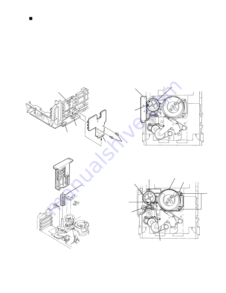
    Removing the cam unit
                                       (See Fig.14 ~17 )

1.
2.

3.
4.

5.
 

Remove the CD loading mechanism assembly.
While turning the cam gear "q", align the pawl "r" 
position of the drive unit to the notch position(Fig.16) on 
the cam gear "q".
Pull out the drive unit and cylinder gear(See Fig.17).
While turning the cam gear "q", align the pawl "s" 
position of the select lever to the notch position(Fig.18) 
on the cam gear "q".
Remove the four screws  J  retaining the cam unit(cam 
gear "q" and cams R1/R2 assembly)(See Fig.18).

Fig.15

Fig.14

Fig.16

Cam gear 

q

Drive unit

r

I

J

J

J

Chassis assembly

Tray select 

switch board

CN802

CN801

CN804

Cylinder gear

Drive unit

Fig.17

Select lever

Cams R1, R2 assembly

Cam unit

Cam gear 

q

s

Summary of Contents for MX-J300

Page 1: ...Disassembly method Adjustment method 1 2 1 3 1 4 1 5 1 24 1 27 1 28 1 28 1 29 COMPACT DIGITAL AUDIO CD 3 CD 2 CD 1 STANDBY VOLUME CD 1 CD 2 CD 3 PLAY EXCHANGER FM AM CD PLAY REC PLAY AUTO REVERSE EJECT COMPACT DIGITAL AUDIO TAPE COMPU PLAY CONTROL FULL LOGIC CONTROL 1 BIT DUAL D A CONVERTER AUX PHONES PANEL OPEN CLOSE POWERED ROLLING PANEL MX J300 EJECT POWER 1 CLEAR CD TAPE CLOCK TIMER POWER SLEE...

Page 2: ...urrnet check Electrical shock hazard testing After re assembling the product always perform an isolation check on the exposed metal parts of the product antenna terminals knobs metal cabinet screw heads headphone jack control shafts etc to be sure the product is safe to operate without danger of electrical shock Do not use a line isolation transformer during this check Plug the AC line cord direct...

Page 3: ...ses invisible laserradiation and is equipped with safety switches whichprevent emission of radiation when the drawer is open and the safety interlocks have failed or are de feated It is dangerous to defeat the safety switches 5 CAUTION If safety switches malfunction the laser is able to function 6 CAUTION Use of controls adjustments or performance of procedures other than those specified herein ma...

Page 4: ...rce can easily destroy the laser diode 4 Handling the traverse unit optical pickup 1 Do not subject the traverse unit optical pickup to strong shocks as it is a sensitive complex unit 2 Cut off the shorted part of the flexible cable using nippers etc after replacing the optical pickup For specific details refer to the replacement procedure in the text Remove the anti static pin when replacing the ...

Page 5: ... body Remove the two screws B on both sides of the body Remove the metal cover from the body while lifting up the rear part of the metal cover 1 2 3 Main body Removing the metal cover See Fig 1 to 3 Disassembly method Fig 3 Fig 2 Fig 1 Metal cover A A A Metal cover B Metal cover B ...

Page 6: ...two screws D from the rear panel Detach upward the rear part of the CD changer mechanism assembly while pulling the front panel assembly and the rear panel outward then pull out the front part backward and upward 1 2 3 4 5 Removing the CD changer mechanism assembly See Fig 4 to 7 Fig 6 Fig 5 Fig 4 Fig 7 Pull outward C Main board CN303 Plastic rivet a CN303 CD changer mechanism assembly Rear panel ...

Page 7: ...d remove the two screws E Release the joint b on the bottom of the body and the joints c and d on both sides of the body using a screwdriver and detach the front panel assembly toward the front 1 2 3 Removing the front panel assembly See Fig 8 to 12 Fig 10 Fig 9 Fig 8 Fig 11 Fig 12 Main board Front panel assembly Main board CN301 CN304 CN305 CN302 CN901A CN901B E Front panel assembly Joint b Front...

Page 8: ...d the six screws H attaching the main board and the heat sink to the rear panel Remove the screw I attaching the rear panel to the base chassis Release the lower two joints e and f on both sides of the rear panel using a screwdriver and detach the rear panel backwards 1 2 3 4 Removing the rear cover and the rear panel See Fig 13 to 16 Fig 13 Fig 14 Fig 15 Fig 16 I Rear panel H G Rear panel F F Rea...

Page 9: ... body remove the screw J attaching the main board to the base chassis 1 2 Removing the main board See Fig 17 to 20 Prior to performing the following procedure remove the rear panel Remove the two screws K and the screw L attaching the heat sink to the main board Remove the IC bracket 1 and 2 on the back of the heat sink Pull out the heat sink toward you 1 2 To remove the heat sink from the main bo...

Page 10: ...e to bundle the wires after repair Remove the four screws M attaching the power transformer assembly When removing the power transformer assembly with the power cord remove the rear panel and pull out the power cord stopper from the bottom chassis upward 1 2 3 Removing the power transformer assembly See Fig 21 to 23 Fig 21 Fig 22 Fig 23 M Power transformer assembly Tie band g CN901A CN901B M Power...

Page 11: ...nel assembly Removing the cassette mechanism assembly See Fig 24 Removing the cassette amplifier board See Fig 25 and 26 When reconnecting the card wire put it pass through under the harness h on the DC motor The Flg 27 shows the details ATTENTION Unsolder the soldering i on the flexible wire for the cassette amplifier board head at the bottom of the cassette mechanism assembly Remove the four scr...

Page 12: ...ull out the rolling panel assembly 1 2 3 4 Prior to performing the following procedure remove the rolling panel assembly Disconnect the card wire from connector CN705 and the harness from CN703 on the display board Remove the two screws R attaching the display board Pull out the display board upward 1 2 3 Removing the rolling panel assembly See Fig 27 to 29 Removing the display board See Fig 30 Fi...

Page 13: ...oard 1 2 Removing each board in the front panel assembly See Fig 31 to 33 Function board 1 Fig 31 and 33 Function board 2 Fig 31 Volume board Fig 31 and 32 Remove the screw W attaching the headphone board 1 Remove the three screws V attaching the power switch board Unsolder FW1002 on the power switch board and disconnect the harness extending from the function board 1 1 2 Remove the four screws U ...

Page 14: ...h sides of the panel holder attaching the bracket and pull out the panel holders outward Detach the multi control board with the cover and the bracket attached Remove the two screws Z attaching the multi control board 1 2 3 Removing the multi control board See Fig 37 to 39 Prior to performing the following procedures remove the metal cover the CD changer mechanism assembly the front panel assembly...

Page 15: ...move the two screws B attaching the shaft bracket Remove the motor belt Pull the parts o on each side of the shaft assembly outwards and detach the shaft assembly upward Detach the drive motor assembly upward 1 2 3 4 5 Removing the drive motor assembly See Fig 40 to 41 Fig 40 Fig 41 B A Motor bracket Shaft bracket Fixing plate n Shaft assembly Motor belt Drive motor assembly Part o Part o ...

Page 16: ... section d fixing the return spring dismount the return spring See Fig 4 Remove the three lock levers See Fig 4 10 11 Fig 1 Fig 2 Fig 3 Fig 4 1 Remove the metal cover 2 Remove the CD changer mechanism assembly 3 From bottom side the CD changer mechanism assembly remove the two screws A retaining the CD servo control board 4 Absorb the four soldered positions a of the right and left motors with a s...

Page 17: ...8 13 14 15 Manually turn the motor pulley in the clockwise direction until the lifter unit stopper is lowered from the section e of CD tray assembly See Fig 8 Pull out all of the three stages of CD tray assembly in the arrow direction f until these stages stop See Fig 6 At the position where the CD tray assembly has stopped pull out the CD tray assembly while pressing the two pawls g and g on the ...

Page 18: ...ction k By raising the CD loading mechanism assembly in the arrow direction l remove the assembly from the lifter unit Fig 10 Fig 12 Fig 11 Fig 13 Removing the CD pick unit See Fig 13 1 2 3 4 Move the cam gear in the arrow direction m Then the CD pickup unit will be moved in the arrow direction n According to the above step shift the CD pickup unit to the center position While pressing the stopper...

Page 19: ... and cylinder gear See Fig 17 While turning the cam gear q align the pawl s position of the select lever to the notch position Fig 18 on the cam gear q Remove the four screws J retaining the cam unit cam gear q and cams R1 R2 assembly See Fig 18 Fig 15 Fig 14 Fig 16 Cam gear q Drive unit r I J J J Chassis assembly Tray select switch board CN802 CN801 CN804 Cylinder gear Drive unit Fig 17 Select le...

Page 20: ...t in the arrow direction remove the gear bracket See Fig 19 From the notch u section on the chassis assembly fixing the edge of gear bracket remove and take out the gear bracket See Fig 20 Remove the belts respectively from the right and left actuator motor pulleys and pulley gears See Fig 19 After turning over the chassis assembly remove the actuator motor while spreading the four pawls v fixing ...

Page 21: ...m gear q See Fig 22 1 2 3 4 Remove the slit washer fixing the cams R1 and R2 assembly By removing the two pawls w fixing the cam R1 separate R2 from R1 Remove the slit washer fixing the cam gear q Pull out the cam gear q from the C G base assembly Removing the C G base assembly See Fig 22 and 23 Remove the three screws L retaining the C G base assembly Fig 23 Slit washer Pawl Cam R2 Slit washer Ca...

Page 22: ...e Fig 1to2 Loosen the screw B attaching the P B head Remove the screws C retaining the R B head assembly 1 2 Removing the R B head assembly See Fig 3 Pull the tab a outward and remove the pinch roller upward 1 Removing the Pinch roller assembly See Fig 4 Fig 1 Fig 3 Fig 2 Fig 4 R P head assembly B A A Pinch roller Sold part Cassette mechanism board C Tab a Refer to the figure for soldering ...

Page 23: ...pstan motor See Fig 5 to 7 Remove the capstan motor Remove the capstan belt ATTENTION Do not stain the belt with grease 1 2 Removing the Capstan belt See Fig 7 Fig 5 Fig 6 Fig 7 Cassette mechanism assembly FR belt D Capstan motor Sold part FR belt Capstan belt Marke red line Motor wire Capstan motor Un solder ...

Page 24: ...coil is used there is no need to adjust the FM tracking 6 The input and output earth systems are separated In case of simultaneously measuring the voltage in both of the input and output systems with an electronic voltmeter for two channels therefore the earth should be connected particularly 7 In the case of BTL connection amplifier the minus terminal of speaker is not for earthing Therefore be s...

Page 25: ...t should be performed in both the forward and reverse directions with the head azimuth screw Constant speed Adjust the volume inside of capstan motor1 so that the frequency counter reading becomes 3 000Hz 60Hz when playing back the test tape VT712 3kHz with the playback mechanism or playback and recording mechanism after ending forward winding of the tape Confirmation of head angle Confirmation of...

Page 26: ... JIS WTD Playback mechanism side Both the playback and recording playback mechanism Both the playback and recording playback mechanism Reference values for confirmation items Items Measurement conditions Measurement method Standard values Adjusting positions 1 While changing over to and from BIAS 1 and 2 confirm that the frequency is changed 2 With the recording and playback mechanism load the tes...

Page 27: ... Automatic measurement of TE amplitude and automatic tuning of TE balance 500mv div 2ms div Fig 1 Approx 3sec pin 25 of IC601 TE Approx 1 8V VREF Tracking error waveform at TOC reading Power ON Play Key Confirm that the Focus error S cuve signal at the pin28 of IC651 is approx 2Vp p Confirm that the signal from pin24 IC651 is 0V as a accelerated pulse during approx 400ms Confirm the waveform of th...

Page 28: ... of the laser diode has expired the following symptoms will appear 1 The level of RF output EFM output ampli tude of eye pattern will below Is the level of RFOUT under 1 25V 0 22Vp p Replace it NO YES O K 3 Semi fixed resistor on the APC PC board The semi fixed resistor on the APC printed circuit board which is attached to the pickup is used to adjust the laser power Since this adjustment should b...

Page 29: ...2 INA CH2 OUTB CH2 OUTA GND OPOUT Driver CH1 output Driver CH1 output Driver CH1 input Driver CH1 gain adjustment Input terminal Connect to the base of external Tr Fixed voltage output Mute control terminal GND Driver CH2 gain adjustment Input terminal Driver CH2 input Driver CH2 output Driver CH2 output Sub slate GND Operation amplifier output Pin NO Pin NO Symbol Symbol 15 16 17 18 19 20 21 22 2...

Page 30: ... PDER PDFR TBAL FBAL EF EF OUT TE TE OUT CROSS TE BPF VDET LD OFF VREF ENV 30 24 25 26 23 22 1 4 3 33 32 34 31 36 35 13 14 15 16 20 2 21 6 29 7 28 27 8 9 10 17 11 12 19 ENV CURCUIT RF DET AGC EQ BDO OFTR VCBA VCBA VCBA VCBA 1 Pin layout 1 2 3 4 5 6 7 8 9 10 11 12 13 14 15 16 17 18 36 35 34 33 32 31 30 29 28 27 26 25 24 23 22 21 20 19 2 Block diagram ...

Page 31: ...rror Inverse input pin for tracking error amp Tracking error signal output Tracking error cross output Input pin of tracking error through BPF Vibration detection signal output Connect to ground Reference voltage output Description APC amp input terminal APC amp output terminal APC ON OFF control terminal Envelope output Ground RF detection signal output Of track status signal output BDO output pi...

Page 32: ...P Switch R E C S W G 1 2 3 4 5 6 7 8 9 P B S W P B S W G R E C S W C O N T G N D V c c 1 2 3 4 5 6 7 8 9 TA8409S IN2 VCC OUT 2 GND GND VS OUT 1 VR IN1 IN1 0 1 0 1 IN2 0 0 1 1 OUT1 H L L OUT2 L H L MOTOR STOP CW CCW CCW CW BRAKE INPUT OUTPUT MODE TA8409S IC851 IC852 Motor driver 1 Pin layout 2 Pin function ...

Page 33: ... Input output port Input output port Data input output Function IF counter signal input IF signal output Not use AM Local OSC signal output FM Local OSC signal input Power suplly VDD 4 5 5 5V When power ON Reset circuit move PLL charge pump output H Local OSC frequency Height than Reference frequency L Low Agreement Height impedance Input for active lowpassfilter of PLL Output for active lowpassfi...

Page 34: ...K MDATA DSL PLL VCO AVDD2 SUB CODE BUFFER SSEL SQCK SUBQ AVDD2 CLVS CRC BLKCK CLDCK SBCK SUBC DEMPH RESY FLAG6 RESY EFM DEMODULATION SUBCODE DEMODULATION SYNC INTERPOLATION 16k SRAM CIRC ERROR CORRECTION DEINTERLEVE LRCKIN MSEL BCLK SSEL SRDATAIN PSEL IOSEL DIGITAL DEEMPHSIS 8TIMES OVER SAMPUNC DIGITAL FILTER 1BIT DAC LOGIC S PEM R PEM L DIGITAL AUDIO INTERFASE DIGITAL AUDIO INTERFASE INTER POLATI...

Page 35: ...ing drive output Focus drive output Reference voltage input pin for D A output block TVD FOD FBA TBAL Focus Balance adjust signal output Tracking Balance adjust signal output Focus error signal input Analog input Tracking error signal input Analog input RF envelope signal input Analog input Vibration detect signal input H detect Off track signal input H off track Track cross signal input RF detect...

Page 36: ...ter input Not used Not used Not used Not used CAM SW input Sub tray SW input Sub tray SW output Connected to GND Disk sensor Test mode Not used Test mode Not used Test mode Not used Test mode Not used Not used L CAM up L CAM down R CAM down R CAM up I I I I I I I I I Description LM DOWN RM UP RMDOWN CHECK CHECK1 CHECK2 CHECK3 connected to GND I O O O I I O O O Statues signal Not used Not used BTL ...

Page 37: ...RP HD RP HD 4 3 27 26 IC2 CAM SW PIC UP IC301 IC701 MICOM SW SP L SP R FL display IC303 HPF IC651 DIGITAL SERVO DIGITAL SIGNAL PROCESSOR IC251 CD CHANGER CONTROL IC601 RF SERVO AMP IC801 DRIVER M M IC401 CN353 22 1 24 PB R PB L 2 23 2 LC1 IC1 Power amp IC304 IC402 CN301 CN351 CN303 CN855 CN805 CN804 CN601 CN701 CN304 CN305 CN702 AM FM DET HEAD SW PLL PB REC AMP Block diagram ...

Page 38: ...3 4 5 MX J300 2 2 Power transformar section F951 3 15A 250V F952 1 6A 250V 1 2 3 4 5 6 7 8 9 FW951 AC PLUG R951 3 3M 1 2W J C Version 120V 50Hz 11 5 13 14 15 8 10 2 9 12 16 6 T951 EI 76 Standerd schematic diagrams ...

Page 39: ...Parts are safety assurance parts When replacing those parts make sure to use the specified TAPE P B signal FM TUNER signal CD signal MAIN signal AM signal SHEET 2 5 SHEET 5 5 SHEET 3 5 SHEET 3 5 SHEET 4 5 Main amplifier section ...

Page 40: ...H A B C D E F G 2 4 MX J300 ntrol section SHEET 3 5 S1002 S1003 S1001 W1006 W1003 LED15 LED14 W1004 W1004 LED11 W1002 W1002 LED12 LED13 W1001 ...

Page 41: ...A B C D E F G 2 5 MX J300 Cassette amplifier section SHEET4 5 SHEET3 5 SHEET2 5 TAPE P B signal ...

Page 42: ...H A B C D E F G 2 6 MX J300 CD signal DIGITAL SERVO DIGITAL SIGNAL PROCESSER CD CHANGER CONTROL RF SERVO AMP CD Servo CD Mechanism control selection SHEET 5 5 SHEET 2 5 ...

Page 43: ...A B C D E F G 2 7 MX J300 Printed circuit boards Main board ...

Page 44: ...H A B C D E F G 2 8 MX J300 Control SW board ...

Page 45: ...A B C D E F G 2 9 MX J300 Cassette amplifier board Power supply board ...

Page 46: ...H A B C D E F G 2 10 MX J300 D servo control board o CD Tray section switch board Cam switch board ...

Page 47: ...EABLE PARTS INSIDE REFER SERVICING TO QUALIFIED SERVICE PERSONNEL RISK OF ELECTRIC SHOCK DO NOT OPEN The lightning flash with arrowhead symbol within an equilateral triangle is intended to alert the user to the presence of uninsulated dangerous voltage within the product s enclosure that may be of sufficient magnitude to constitute a risk of electric shock to persons The exclamation point within a...

Page 48: ...le Canada THIS DIGITALAPPARATUS DOES NOT EXCEED THE CLASS B LIMITS FOR RADIO NOISE EMISSIONS FROM DIGITAL APPARATUSAS SET OUT IN THE INTERFERENCE CAUSING EQUIPMENT STANDARD ENTITLED DIGITALAPPARATUS ICES 003 OF THE DEPARTMENT OF COMMUNICATIONS CET APPAREIL NUMERIQUE RESPECTE LES LIMITES DE BRUITS RADIOELECTRIQUES APPLICABLES AUX APPAREILS NUMIRIQUES DE CLASSE B PRESCRITES DANS LA NORME SUR LE MATE...

Page 49: ... internal heat built up in the unit Leave sufficient distance between the unit and the TV Keep the speakers away from the TV to avoid interference with TV DO NOT install the unit in a location near heat sources or in a place subject to direct sunlight excessive dust or vibration We would like to thank you for purchasing one of our JVC products Before operating this unit read this manual carefully ...

Page 50: ... and AM Broadcasts 14 Tuning in a Station 14 Presetting Stations 14 Tuning in a Preset Station 14 Playing Back CDs 15 Loading CDs 15 Playing Back the Entire Discs Continuous Play 15 Basic CD Operations 15 Programming the Playing Order of the Tracks Program Play 16 Playing at Random Random Play 17 Repeating Tracks or CDs Repeat Play 18 Prohibiting Disc Ejection Tray Lock 18 Playing Back Tapes 19 Pl...

Page 51: ...E POWERED ROLLING PANEL MX J300 EJECT PANEL OPEN CLOSE j k x c o a s d f h v l i REC START STOP DEMO DUBBING CD REC START PROGRAM RANDOM REPEAT PRESET TUNING REVERSE MODE TAPE A B SOUND MODE ACTIVE BASS EX CLOCK TIMER DISPLAY SET CANCEL z g POWER Location of the Buttons and Controls Become familiar with the buttons and controls on your unit Powered Rolling Panel Press PANEL OPEN CLOSE to open the ...

Page 52: ... 11 22 o CLOCK TIMER button 11 22 PRESET buttons 14 4 reverse search forward search buttons 11 16 22 4 fast left fast right buttons 19 a REC START STOP button 20 s DUBBING button 21 d CD REC START button 21 f REVERSE MODE button 19 21 g TAPE A B button 19 h 7 stop button 15 19 j CANCEL button 11 17 23 DEMO button 10 k DISPLAY button 11 l TUNING buttons 14 These buttons do not function as 1 PROGRAM...

Page 53: ...ING REVERSE MODE TAPE A B SOUND MODE ACTIVE BASS EX j t CD 3 CD 2 CD 1 STANDBY VOLUME CD 1 CD 2 CD 3 PLAY EXCHANGER FM AM CD PLAY REC PLAY AUTO REVERSE EJECT COMPACT DIGITAL AUDIO TAPE COMPU PLAY CONTROL FULL LOGIC CONTROL 1 BIT DUAL D A CONVERTER AUX PHONES MX J200 EJECT l g e p 8 z k h Become familiar with the buttons and controls on your unit CA MXJ200 ...

Page 54: ... VOLUME control 12 s CANCEL button 11 17 23 DEMO button 10 Display Window REC SLEEP DAILY A B REC S MODE kHz MHz 2 3 1 BASS ALL1CD PRGM RANDOM REPEAT MONO ST 1 1 2 3 4 7 5 8 9 6 d DISPLAY button 11 f TUNING buttons 14 These buttons do not function as 1 g PROGRAM button 16 21 h CD 6 play pause button and lamp 15 Pressing this button also turns on the unit j RANDOM button 17 k FM AM button and lamp ...

Page 55: ...ELECT button 11 23 25 5 SELECT button 11 23 25 6 SET button 11 23 25 7 Disc number buttons CD 1 CD 2 and CD 3 15 16 21 Pressing one of these buttons also turns on the unit 8 forward search button 11 16 22 9 4 reverse search button 11 16 22 p fast right button 19 q 1 fast left button 19 w REC PAUSE button 20 e SHIFT button 11 23 25 r SOUND MODE button 13 t POWER button 12 y SLEEP button 26 u AUX bu...

Page 56: ...the batteries in the battery compartment when you are not going to use the remote control for an extended period of time Otherwise it will be damaged from battery leakage R6P R6PU SUM 3 AA 15F Connecting Antennas FM antenna FM antenna supplied Outdoor FM antenna not supplied 7 16 in 10 mm Extend the FM antenna supplied horizontally If reception is poor Connect the outdoor antenna Before attaching ...

Page 57: ...ords Keep the antennas away from metallic parts of the unit connecting cords and the AC power cord AM antenna Vinyl covered wire not supplied AM loop antenna supplied Connecting Speakers You can connect a pair of the front speakers Right speaker Left speaker Black Red 1 Press and hold the clamp of the speaker terminal on the rear of the unit 2 Insert the end of the speaker cord into the terminal M...

Page 58: ... are complete To connect audio equipment Connect the audio output jacks on the other equipment and the AUX IN jacks on the rear using an audio cord not supplied To audio output NOW you can plug in the unit and other connected equipment FINALLY To a wall outlet When connecting the AC power cord into a wall outlet the unit automatically starts display demonstration To stop the display demonstration ...

Page 59: ...ST REC SOUND MODE BASS 2 Press SELECT or to adjust the hour then press SET If you want to correct the hour after pressing SET press CANCEL on the unit The hour digits start flashing again 3 Press SELECT or to adjust the minute then press SET To check the clock time Press DISPLAY while playing any source Each time you press the button the source indication and the clock time alternate on the displa...

Page 60: ...ular source FM AM CD 6 AUX and TAPE 2 3 the unit turns on For MX J300 only the Powered Rolling Panel opens automatically The unit starts playing the source if it is ready COMPU PLAY CONTROL To listen to the FM AM broadcasts press FM AM See page 14 To play back CDs press CD 6 See pages 15 18 To play back tapes press TAPE 2 3 See page 19 To select the external equipment as the source press AUX To tu...

Page 61: ...nd cannot be used for recording To select the sound modes press SOUND MODE until the sound mode you want appears on the display The S MODE indicator also lights up on the display Each time you press the button the sound modes change as follows Surround modes D CLUB Increases resonance and bass HALL Adds depth and brilliance to the sound STADIUM Adds clarity and spreads the sound like in an outdoor...

Page 62: ...uner preset function before shipment This is not a malfunction You can preset the stations you want into memory by following the presetting method There is a time limit in doing the following steps If the setting is canceled before you finish start from step 1 again 1 Tune in the station you want to preset See Tuning in a Station above 2 Press SET 3 Press PRESET to select a preset number 4 Press S...

Page 63: ...ly 1 Load CDs 2 Press one of the disc number buttons CD 1 CD 2 and CD 3 for the disc you want to play CD play starts from the first track of the selected disc Pressing CD 6 instead of the disc number buttons starts playing back if a CD is on the trays To stop during play press 7 on the unit or CD 7 CLEAR on the remote control To remove the disc press 0 for the corresponding disc tray CD playback s...

Page 64: ...r press CD 6 then 7 on the unit or CD 7 CLEAR on the remote control before going to the next step 2 Select the Program play mode On the unit Press PROGRAM On the remote control Press PLAY MODE repeatedly until the PRGM indicator lights on the display Each time you press the button the CD play mode changes as follows Program play Ramdom play Continuous play back to the beginning If a program has be...

Page 65: ...o program a 33rd step FULL will appear on the display If your entry is ignored You have tried to program a track from an empty tray or a track number that does not exist on the CD for example selecting track 14 on a CD that only has 12 tracks Such entries are ignored ST REC SOUND MODE 2 3 1 BASS RANDOM RANDOM CD PLAY MODE Playing at Random Random Play The tracks of all loaded CDs will play at rand...

Page 66: ... Repeats one track on one CD REPEAT 1CD is not used for Program play and Random play To cancel Repeat play press REPEAT repeatedly until the REPEAT indicator REPEAT ALL REPEAT 1CD or REPEAT 1 goes off from the display Repeat play is also canceled when you press PROGRAM or RANDOM Prohibiting Disc Ejection Tray Lock You can prohibit CD ejection from the unit and can lock discs This operation is poss...

Page 67: ... not on See To play both sides repeatedly Reverse Mode To stop during play press 7 To operate the other deck press TAPE A B or TAPE A or TAPE B on the remote control then TAPE 2 3 Playing Back Tapes For deck A For deck B To fast wind to the left or to the right press 4 or or 1 or on the remote control The tape direction indicator 2 3 starts flashing quickly on the display To remove the cassette pr...

Page 68: ...To stop during recording press REC START STOP again or press 7 REC PAUSE 2 3 TAPE REC START STOP IMPORTANT It should be noted that it may be unlawful to re record pre recorded tapes records or discs without the consent of the owner of copyright in the sound or video recording broadcast or cable programme and in any literary dramatic musical or artistic embodied therein The recording level is autom...

Page 69: ...ote control The REC indicator flashes on the display To resume recording press TAPE 2 3 on the unit or TAPE 2 or TAPE 3 on the remote control The REC indicator stops flashing and remains lit To remove the cassette press EJECT 0 for deck B To record on both sides Reverse Mode Press REVERSE MODE so that the Reverse Mode indicator lights up as When using the Reverse Mode for recording start recording...

Page 70: ...dicator also starts flashing on the display Each time you press the button the timer setting mode changes as follows 2 Press CLOCK TIMER again ON TIME appears for 2 seconds then the unit enters on time setting mode 3 Set the on time you want the unit to turn on 1 Press 4 or to set the hour then press SET 2 Press 4 or to set the minute then press SET OFF TIME appears for 2 seconds then the unit ent...

Page 71: ...ly Timer remains in memory To turn on the Daily Timer press SET The DAILY indicator lights up on the display The settings you have done are shown on the display in sequence for your confirmation If the unit is turned on when the timer on time comes Daily Timer does not work PRESET SET PRESET DAILY ST REC SOUND MODE BASS TIMER 2 On the remote control 1 Press SHIFT 2 Press TIMER The DAILY indicator ...

Page 72: ...settings you have done are shown on the display in sequence DAILY ST REC SOUND MODE BASS Using Recording Timer With Recording Timer you can make a tape of a radio broadcast automatically How Recording Timer actually works The unit automatically turns on tunes into the specified station sets the volume level to MIN and starts recording when the on time comes the indicator flashes just before the on...

Page 73: ...it only The REC indicator goes off and OFF appears on the display The Recording Timer is canceled but the setting for the Recording Timer remains in memory To turn on the Recording Timer press SET The REC indicator lights up on the display The settings you have done are shown on the display in sequence for your confirmation PRESET SET PRESET SET TIMER 2 On the remote control 1 Put a recordable cas...

Page 74: ...imer is operating Sleep Timer will not work the SLEEP indicator does not go off does not work SLEEP 10 Canceled 20 30 60 90 120 Using Sleep Timer With Sleep Timer you can fall asleep to music You can set Sleep Timer when the unit is turned on How Sleep Timer actually works The unit automatically turns off after the specified time length passes On the remote control ONLY 1 Press SLEEP The time leng...

Page 75: ...ete erasure Difficulty in recording To clean the heads capstans and pinch rollers Use a cotton swab moistened with alcohol To demagnetize the heads Turn off the unit and use a head demagnetizer available at electronics and record shops Heads Capstans Pinch rollers Handling discs Remove the disc from its case by holding it at the edge while pressing the center hole lightly Do not touch the shiny su...

Page 76: ... the disc See page 27 Plug the AC power cord Unlock the trays See page 18 Place the disc with the label side up Turn on the unit Cover the holes with adhesive tape Unplug the AC power cord and then plug it back in Remove the obstruction Replace the batteries Specifications Amplifier section Output Power CA MXJ300 100 W per channel min RMS driven into 6 Ω at 1 kHz with no more than 10 total harmoni...

Page 77: ...E CENTER LOCATIONS 107 Little Falls Road Fairfield NJ 07004 2105 973 808 9279 5665 Corporate Avenue Cypress CA 90630 0024 714 229 8011 13 Cummings Park Woburn MA 01801 781 376 9100 705 Enterprise Street Aurora IL 60504 8149 630 851 7855 10700 Hammerly Suite 110 Houston TX 77043 713 935 9331 890 Dubuque Avenue South San Francisco CA 94080 1804 650 871 2666 1500 Lakes Parkway Lawrenceville GA 30243 ...

Page 78: ...any attachment not provided with the products or if the model or serial number has been altered tampered with defaced or removed 2 Initial installation and installation and removal for repair 3 Operational adjustments covered in the Owner s Manual normal maintenance video and audio head cleaning 4 Damage that occurs in shipment due to act of God and cosmetic damage 5 Signal reception problems and ...

Page 79: ...VICTOR COMPANY OF JAPAN LIMITED 0200KSMMDWHIT EN J VC ...

Reviews: