JVC LT-32WX84 Service Manual Download Page 72

Quick Setup                                     Connections

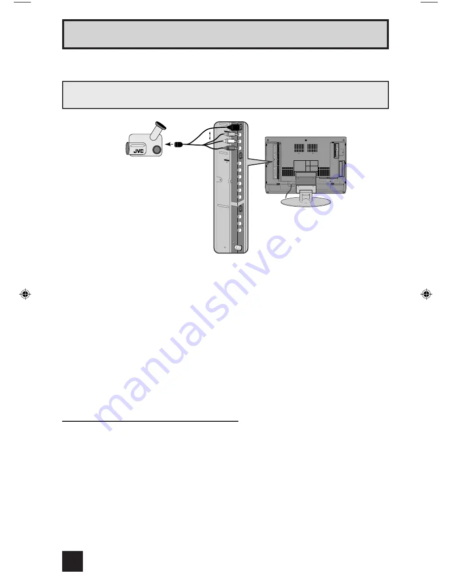
1)   Connect a yellow composite cable from the camcorder VIDEO OUT, into the VIDEO IN on 

the back of the TV, 

OR

 connect an S-Video cable from the camcorder to the back of the TV.

2)   Connect a white cable from the camcorder LEFT AUDIO OUT, into the LEFT AUDIO IN on 

the back of the TV.

3)   Connect a red cable from the camcorder RIGHT AUDIO OUT, into the RIGHT AUDIO IN on 

the back of the TV.

Note:

•   If your camcorder is a mono sound model it will have only one AUDIO OUT. Connect it to the 

LEFT AUDIO IN on the back of the TV. 

You can connect a camcorder to you televison by using the input jacks located on the back of 
the television.

�������������

��������������

��������������

���������

��

�����

����� �

�����

�������

����

�����

�����

����� �

�����

�������

����

�����

�����

������� ��

�����

�������

�����

��
���������

�����

�����

�� ���� �����

16

Connecting to a Camcorder

Headphone Connection

You can connect a pair of headphones to the television using the headphone jack located on 
the side of the television.

1)   Plug a headphone jack into the headphone jack on the television’s side panel.

LT-32WX84 Eng

1/21/04, 2:42 PM

16

Summary of Contents for LT-32WX84

Page 1: ...17 5 TROUBLESHOOTING 1 49 BASIC CHASSIS SB5 INPUT 1 INDEX ASPECT FREEZE SWAP SELECT RETURN INPUT 2 INPUT 3 DIGITAL IN THEATER PRO NATURAL CINEMA VIDEO STATUS SLEEP TIMER DISPLAY SOUND LIGHT TV CATV VCR DVD MUTING MENU BACK C C RM C13G REW VCR CHANNEL PREV NEXT VCR DVD POWER TV VCR FF PLAY REC PAUSE OPEN CLOSE STILL PAUSE STOP CH CH VOL VOL OK MULTI SCREEN SPLIT V1 V2 V3 D IN 1 2 3 4 5 6 7 8 9 0 10...

Page 2: ... Diagonal 80 2cm H 41 2cm V 68 7cm Display Pixels Horizontal 1280 dots Vertical 768 dots W XGA Audio Power Output 10W 10W Speaker 6 6cm round type 2 Oblique corn Antenna terminal VHF UHF F type connector 75Ω unbalanced coaxial Video Audio input Input 1 2 3 Component Video Input 1 1125i 750p 525p 525i S Video Input 1 2 Video Audio RCA pin jack 3 Y 1V p p Sync signal 0 35V p p 3 value sync 75 Ω Pb P...

Page 3: ... is required observe the original lead dress Extra precaution should be given to assure correct lead dress in the high voltage circuit area Where a short circuit has occurred those components that indicate evidence of overheating should be replaced Always use the manufacturer s replacement components 9 Isolation Check Safety for Electrical Shock Hazard After re assembling the product always perfor...

Page 4: ...t against accidents and earthquakes 1 2 3 INSTALLATION REQUIREMENTS To ensure safety in an emergency such as an earthquake and to prevent accidents ensure that measures are taken to prevent the TV dropping or falling over Use the supplied screws to firmly attach the supplied hooks OPTION to the back of the TV and use commercially available cord to fix the TV to rigid components such as walls and c...

Page 5: ...during transportation and storage as the LCD panel is very vulnerable to lateral impacts and may break During transportation ensure that the unit is loaded along the traveling direction of the vehicle and avoid stacking them on one another For storage ensure that they are stacked in 2 layers or less even when placed upright 1 3 2 OPTICAL FILTER ON THE FRONT OF THE LCD PANEL 1 Avoid placing the uni...

Page 6: ...ark fault and flicker fault that are respectively defined as follows 1 BRIGHT FAULT In this pixel fault a cell that should not light originally is lighting on and off For checking this pixel fault input ALL BLACK SCREEN and find out the cell that is lighting on and off 2 DARK FAULT In this pixel fault a cell that should light originally is not lighting or lighting with the brightness twice as brig...

Page 7: ... Not used 19 TU_POW O Not used 20 VCOI I LPF input 21 PDO O LPF output 22 IP_RESET O Reset L Reset L 23 OSD_YM O YM for OSD CLOSED CAPTION 24 OSD_B O B signal output for OSD CLOSED CAPTION 25 POW_LED O Lighting for power Lighting H 26 OSD_G O G for OSD CLOSED CAPTION 27 OSD_R O R for OSD CLOSED CAPTION 28 VRE I Reference voltage 29 IP_ERR I AMDP program load 30 IREF I Reference current 31 COMP I R...

Page 8: ...I Mechanical POWER swtich detection Pussing L 62 MAIN_POW O Main power control ON L 63 NC Not used 64 B1_POW O Not used 65 AFT1 Not used 66 X_RAY I GND 67 EE_CDS I GND 68 KEY2 I Key scan data ON H 69 KEY1 I Key scan data ON H 70 SCL1 O I2C bus clock For Main memory 71 SDA1 I O I2C bus data For Main memory 72 REMO I Remote control data 73 AP_REQ LED_2 O Not used 74 VSS I GND 75 OSC2 O 4MHz oscillat...

Page 9: ... 17 I2C_STOP O Not used 18 BL_ON O Back light reset for LCD panel Reset L 19 NC O Not used 20 NC O Not used 21 NC O Not used 22 NC O Not used 23 SDA1 I O I2C bus data For Sub memory 24 A DIM O Not used 25 SCL1 O I2C bus clock For Sub memory 26 SDA0 I O I2C bus data For general 27 SCL0 O I2C bus clock For general 28 NC O Not used 29 NC O Not used 30 NC O Not used 31 NC O Not used 32 NC O Not used 3...

Page 10: ... communication Main cpu 51 NC O Not used 52 ACTIVE I Not used 53 VD I Vertical sync 54 REC_DET I Not used 55 PSS I Not used 56 ALARM I Not used 57 SYSTEM2 I Not used 58 SYSTEM1 I Not used 59 PROTECTOR1 I Not used 60 AMP_PRO2 I Not used 61 AMP_PRO1 I Not used 62 EE_CDS I Not used 63 KEY_IN1 I Not used 64 KEY_IN2 I Not used Pin No Pin name I O Function ...

Page 11: ...ve the FAN BRACKET 1 Remove the 3 screws M and remove the JACK BASE 2 Remove the 5 screws N and remove the VIDEO PWB SHIELD 3 Remove the 2 screws P and remove the VIDEO PWB 4 Remove the 5 screws R and remove the VIDEO PWB BRACKET 5 Remove the 4 screws S and remove the MI COM DIST MODULE PWB form the VIDEO PWB BRACKET 3 1 7 REMOVING THE POWER PWB Remove the STAND Remove the REAR COVER Remove the FA...

Page 12: ...OWER PWB RECEIVER PWB BRACKET VIDEO PWB BRACKET CHASSIS BASE A B C E D P Q Z M N N R R R S U V V W X T X T T L K H G J JACK COVER JACK COVER STAND STAND COVER POWER CORD FAN BRACKET POWER CORD HOLDER REGULATOR PWB TERMINAL BASE RECEIVER PWB COOLING FAN FRONT CONTROL PWB FRONT SENSOR PWB CONTROL KNOB MI COM DIST MODULE PWB c F Y Y ...

Page 13: ...MI COM DIST MODULE PWB Remove the POWER PWB 1 Remove the 3 screws d the 2 screws e and the 2 screws f 7 screws in total Then remove the FRAME R 2 Remove the 3 screws g and the 2 screws h 4 screws in total Then remove the FRAME L 3 Remove the 3 screws j Then remove the CENTER FRAME 4 Remove the 2 screws k and the 1 screw m 3 screws in total Then remove the TOP FRAME 5 Remove the 4 screws n and the ...

Page 14: ...G REW VCR CHANNEL PREV NEXT VCR DVD POWER TV VCR FF PLAY REC PAUSE OPEN CLOSE STILL PAUSE STOP CH CH VOL VOL OK MULTI SCREEN SPLIT V1 V2 V3 D IN 1 2 3 4 5 6 7 8 9 0 100 TV C C POWER INPUT 4 V4 POWER VCR DVD switch NUMBER FUNCTION UP FUNCTION RIGHT FUNCTION DOWN DISPLAY FUNCTION LEFT TV CATV switch MENU SLEEP TIMER MEMORY MUTING VIDEO STATUS BACK Setting items Settings Item No 1 PICTURE SOUND sound...

Page 15: ...NT DETAIL COLOR TEMPERATURE DIG NOISE CLEAR COLOR MANAGEMENT DINAMIC 00 04 11 02 05 HIGH OFF VIVID STANDARD 00 00 00 00 00 LOW OFF STD GAME 00 05 05 00 0 HIGH OFF STD THEATER 00 00 00 00 00 HIGH OFF STD Setting item PICTURE BRIGHT COLOR TINT DETAIL COLOR TEMPERATURE DIG NOISE CLEAR COLOR MANAGEMENT DINAMIC 00 03 12 00 03 HIGH OFF VIVID STANDARD 00 00 00 00 00 LOW OFF STD GAME 00 05 05 00 00 HIGH O...

Page 16: ...he tweezers and remove the chip part Transistors diodes variable resistors etc 1 Apply extra solder to each lead 2 As shown in the figure push the part with tweezers and alternately melt the solder at each lead Shift and remove the chip part NOTE After removing the part remove remaining solder from the pattern 2 How to install Chip parts Resistors capacitors etc 1 Apply solder to the pattern as in...

Page 17: ...ms of this service adjustment 7 Preparation for adjustment Unless otherwise specified in the adjustment items preset the following functions with the REMOTE CONTROL UNIT 4 2 MEASURING INSTRUMENT AND FIXTURES DC voltmeter or digital voltmeter Oscilloscope Signal generator Pattern generator NTSC 525i 525p 750p 1125i DIGITAL TV audio multiplex signal generator Remote control unit 4 3 ADJUSTMENT ITEMS...

Page 18: ... CN300U CN3003 PW CN000K CN8003 CN1001 POWER PWB POWER CORD SPEAKER L SPEAKER R RECEIVER PWB TOP INVERTER UNIT BOTTOM INVERTER UNIT FRONT CONTROL PWB FRONT SENSOR PWB MI COM DIST MODULE PWB REGULATOR PWB VIDEO PWB COOLING FAN CONTROL PWB LCD PANEL UNIT CN1 COOLING FAN P Q TU1101 CN8 CN2 CN7 CN10 CN109 CN106 CN101 DIGITAL INPUT MODULE PWB Q SR DC AQ ...

Page 19: ...L MUTE NTSC CINE ST L FL MUTE 9 IP DRV R069 B054 CUT R078 G079 B079 BR 3 WHITE BALANCE VOLUME key CHANNEL key YCM001 185 YCS001 114 A01 A27 DO NOT ADJUST DO NOT ADJUST DO NOT ADJUST ADM001 034 PPA001 008 PPB001 036 PPC001 008 PPD001 025 DDT01 34 CMT01 57 IPA001 120 IPB001 079 IPC001 044 IPD001 026 IPE001 015 S01 S99 D01 D32 IN APL PDA001 7 PANEL OUT MIN TEM MAX F01 F59 F01 D01 S01 A01 A01 001 YCM0...

Page 20: ...LANCE This sets the setting values of the WHITE BALANCE Do not adjust 4 MEMORY SETUP This sets the setting values of the MEMORY ADDRESS Do not adjust 5 RF AFC This is used when the IF VCO is adjusted Do not adjust 6 DD CM This sets the setting values of the panel image processing Do not adjust 7 PANEL This sets the setting values of the panel power limit control Do not adjust 8 PP This sets the se...

Page 21: ...E White balance setting Setting for this item is not required in servicing 4 MEMORY SETUP Memory setting Do not change settings 5 RF AFC Setting for this item is not required in servicing 6 DD CM Do not change settings Adjustment of color manegment and device driver 7 PANEL Panel power limit control Do not change settings 8 PP Multi screen processing setting Do not change settings of items that ar...

Page 22: ...play 000 007 004 A11 Not display 000 063 063 A12 Not display 000 063 063 A13 Not display 000 003 000 A14 Not display 000 007 000 A15 Not display 000 003 000 A16 Not display 000 003 000 A17 Not display 000 003 000 A18 IN LEVEL 000 015 006 A19 LOW SEP 000 063 041 A20 HI SEP 000 063 018 A21 Not display 000 001 000 A22 Not display 000 001 000 A23 Not display 000 001 000 A24 Not display 000 001 000 A25...

Page 23: ...ER STANDARD THEATER S19 CUTR 000 255 128 128 128 128 128 128 128 128 S20 OF CUTR 127 128 000 000 000 000 000 000 000 000 S21 CUTG 000 255 128 128 128 128 128 128 128 128 S22 OF CUTG 127 128 000 000 000 000 000 000 000 000 S23 CUTB 000 255 128 128 128 128 128 128 128 128 S24 OF CUTB 127 128 000 000 000 000 000 000 000 000 S25 CUTR 000 001 000 000 000 000 000 000 000 000 S26 CUTG 000 001 000 000 000...

Page 24: ...R 000 255 000 000 S58 BHSTR 000 015 000 000 S59 BHEND 000 255 000 000 S60 BHEND 000 015 000 000 Item No Item Variable range Setting value NTSC 525i 525p 750p 1125i STANDARD THEATER STANDARD THEATER STANDARD THEATER S61 PLPOL2 000 001 001 001 001 001 001 001 S62 PLEV2 000 127 016 015 016 015 016 016 S63 PLPOL1 000 001 000 000 000 000 000 000 S64 PLEV1 000 127 000 000 000 000 000 000 Item No Item Va...

Page 25: ...play 000 001 000 D13 Not display 000 001 000 D14 Not display 000 001 000 D15 Not display 000 001 000 D16 Not display 000 001 000 D17 Not display 000 001 000 D18 Not display 000 001 000 D19 Not display 000 001 000 D20 Not display 000 001 000 D21 Not display 000 001 000 D22 Not display 000 001 000 D23 Not display 000 001 000 D24 Not display 000 001 000 D25 Not display 000 001 000 D26 Not display 000...

Page 26: ... Not display 000 063 039 040 037 024 024 Item No Item Variable range Setting value F44 Not display 000 001 000 F45 Not display 000 007 000 F46 OUT LV 000 255 090 F47 LIMIT B 000 255 000 F48 LIMIT A 000 255 000 F49 Not display 000 255 123 F50 Not display 000 255 155 F51 Not display 000 255 123 F52 Not display 000 255 255 F53 Not display 000 001 001 F54 Not display 000 001 001 F55 Not display 000 00...

Page 27: ...000 255 096 YCM036 Not display 000 001 001 YCM037 Not display 000 003 001 YCM038 Not display 000 127 062 YCM039 Not display 000 127 073 YCM040 Not display 000 003 002 YCM041 Not display 000 063 016 YCM042 Not display 000 001 000 YCM043 Not display 000 001 000 YCM044 Not display 000 255 200 YCM045 Not display 000 001 000 YCM046 Not display 000 255 147 YCM047 Not display 000 001 001 YCM048 Not displ...

Page 28: ...002 YCM126 Not display 000 001 000 YCM127 Not display 000 001 001 Item No Item Variable range Setting value YCM128 Not display 000 001 001 YCM129 Not display 000 001 001 YCM130 Not display 000 003 001 YCM131 Not display 000 255 040 YCM132 Not display 000 255 155 YCM133 Not display 000 255 055 YCM134 Not display 000 007 001 YCM135 Not display 000 255 136 YCM136 Not display 000 001 000 YCM137 Not di...

Page 29: ...9 Not display 000 007 002 YCS030 Not display 000 003 003 Item No Item Variable range Setting value YCS031 Not display 000 001 000 YCS032 Not display 000 003 003 YCS033 Not display 000 001 001 YCS034 Not display 000 001 000 YCS035 Not display 000 255 096 YCS036 Not display 000 001 001 YCS037 Not display 000 003 001 YCS038 Not display 000 127 062 YCS039 Not display 000 127 073 YCS040 Not display 000...

Page 30: ...003 001 YCS111 Not display 000 003 001 YCS112 Not display 000 003 001 YCS113 Not display 000 003 001 YCS114 Not display 000 255 000 Item No Item Variable range Setting value INPUT SIGNAL NTSC ASPECT FULL MULTI SCREEN SINGLE VIDEO STATUS STANDARD COLOR TEMPERATURE LOW Item No Item Variable range Setting value BR Not display 000 238 000 DRV R Not display 000 255 000 DRV B Not display 000 255 000 CUT...

Page 31: ... Not display 032 031 000 CMT33 Not display 128 127 001 CMT34 Not display 128 127 015 CMT35 Not display 128 127 003 CMT36 Not display 128 127 015 CMT37 Not display 000 255 064 CMT38 Not display 000 255 068 Item No Item Variable range Setting value CMT39 Not display 000 255 078 CMT40 Not display 128 127 000 CMT41 Not display 128 127 000 CMT42 Not display 000 001 000 CMT43 Not display 000 0FF 080 CMT...

Page 32: ...able range Setting value PPB001 Not display 000 031 000 Item No Item Variable range Setting value PPB002 Not display 000 255 000 PPB003 Not display 000 255 000 PPB004 Not display 000 031 000 PPB005 Not display 000 255 014 PPB006 Not display 000 255 000 PPB007 Not display 000 031 000 PPB008 Not display 000 255 028 PPB009 Not display 000 255 000 PPB010 Not display 000 031 000 PPB011 Not display 000 ...

Page 33: ...0 003 000 IPA007 Not display 000 015 00F Item No Item Variable range Setting value IPA008 Not display 000 063 002 IPA009 Not display 000 063 003 IPA010 Not display 000 063 01B IPA011 Not display 000 063 019 IPA012 Not display 000 063 029F IPA013 Not display 000 003 000 IPA014 Not display 000 003 000 IPA015 Not display 000 063 00F IPA016 Not display 000 063 003 IPA017 Not display 000 001 001 IPA018...

Page 34: ...y 000 015 000 IPA096 Not display 000 255 000 IPA097 Not display 000 015 005 Item No Item Variable range Setting value IPA098 Not display 000 255 0DB IPA099 Not display 000 015 000 IPA100 Not display 000 255 000 IPA101 Not display 000 015 000 IPA102 Not display 000 255 000 IPA103 Not display 000 015 000 IPA104 Not display 000 255 000 IPA105 Not display 000 015 000 IPA106 Not display 000 255 000 IPA...

Page 35: ...ay 000 255 000 IPB064 Not display 000 255 080 IPB065 Not display 000 255 080 Item No Item Variable range Setting value IPB066 Not display 000 001 000 IPB067 Not display 000 015 000 IPB068 Not display 000 015 000 IPB069 Not display 000 015 000 IPB070 Not display 000 015 00F IPB071 Not display 000 255 000 IPB072 Not display 000 015 000 IPB073 Not display 000 255 000 IPB074 Not display 000 001 000 IP...

Page 36: ...00 255 00E IPD025 Not display 000 015 004 IPD026 Not display 000 255 0C0 Item No Item Variable range Setting value Item No Item Variable range Setting value IPE001 Not display 000 255 001 IPE002 Not display 000 255 002 IPE003 Not display 000 255 001 IPE004 Not display 000 255 002 IPE005 Not display 000 255 001 IPE006 Not display 000 255 002 IPE007 Not display 000 255 001 IPE008 Not display 000 255...

Page 37: ...HDM066 Not display 000 001 000 HDM067 Not display 000 001 000 HDM068 Not display 000 031 000 HDM069 Not display 000 001 000 HDM070 Not display 000 001 000 HDM071 Not display 000 001 000 HDM072 Not display 000 001 000 Item No Item Variable range Setting value HDM073 Not display 000 001 000 HDM074 Not display 000 031 000 HDM075 Not display 000 001 000 HDM076 Not display 000 001 000 HDM077 Not displa...

Page 38: ...078 Not display 000 RHD079 Not display 000 RHD080 Not display 000 Item No Item Variable range Setting value RHD081 Not display 000 RHD082 Not display 000 RHD083 Not display 000 RHD084 Not display 000 RHD085 Not display 000 RHD086 Not display 000 RHD087 Not display 000 RHD088 Not display 000 RHD089 Not display 000 RHD090 Not display 000 RHD091 Not display 000 RHD092 Not display 000 RHD093 Not displ...

Page 39: ...ay 000 RHD145 Not display 000 RHD146 Not display 000 RHD147 Not display 000 RHD148 Not display 000 RHD149 Not display 000 RHD150 Not display 000 RHD151 Not display 000 RHD152 Not display 000 RHD153 Not display 000 RHD154 Not display 000 RHD155 Not display 000 RHD156 Not display 000 RHD157 Not display 000 RHD158 Not display 000 RHD159 Not display 000 RHD160 Not display 000 RHD161 Not display 000 RH...

Page 40: ...use the values change according to the reference adjustment values you do not have to take note of the values if unnecessary 3 Unless otherwise specified in the adjustment instructions preset the following functions with the remote control unit NOTE Follow the order instructed in adjustment procedure Item setting value contents S19 128 R CUT OFF S21 128 G CUT OFF S23 128 B CUT OFF Item Initial val...

Page 41: ...ture control mode sw to 000 to set Y ADJUST MAX MODE 7 Set F46 Output level upon detection F47 Minimum value upon detection and F48 Maximum value upon detection to values as shown in the left table 8 Press the MUTING key to memoirze the set value 9 Select 8 PP from the SERVICE MODE 10 Adjust ADM013 G OFFSET to set the 0 black part on the upper half of the screen to maximum brightness Fig 2 11 Add ...

Page 42: ...46 Output level upon detection F47 Minimum value upon detection and F48 Maximum value upon detection to values as shown in the left table 8 Press the MUTING key to memoirze the set value 9 Select 8 PP from the SERVICE MODE 10 Adjust ADM010 G GAIN to set the upper half of the screen to maximum brightness Fig 3 11 Press the MUTING key to memoirze the set value 12 Check the black level Perform the BL...

Page 43: ...lue in the range of 5 to set the upper half of the screen magenta 11 Adjust ADM012 R OFFSET to change the upper half of the screen from magenta to blue 12 Take a note of the value of ADM012 R OFFSET adjusted in 11 13 Change the value of ADM012 R OFFSET from the value that you have taken note of in the range of 5 to set the upper half of the screen magenta 14 Adjust ADM014 B OFFSET to change the up...

Page 44: ...6 Set F44 Picture control to 001 and F45 Picture control mode sw to 000 to set Y ADJUST MAX MODE 7 Set F46 Output level upon detection F47 Minimum value upon detection and F48 Maximum value upon detection to values as shown in the left table 8 Select 2 YC SEP from the SERVICE MODE 9 Adjust YCM131 BRIGHTNESS so that 0 part of gradation is the brightest Fig 5 10 Press the MUTING key to memoirze the ...

Page 45: ...ction F47 Minimum value upon detection and F48 Maximum value upon detection to values as shown in the left table 8 Select 2 YC SEP from the SERVICE MODE 9 Adjust YCM132 CONTRAST so that the 75 white of gradation is white Fig 6 10 Press the MUTING key to memoirze the set value 11 Check the black level adjusted in composite input black level adjustment Perform the Composite input black level Adjustm...

Page 46: ...trol mode sw to 000 to set Y ADJUST MAX MODE 8 Set F46 Output level upon detection F47 Minimum value upon detection and F48 Maximum value upon detection to values as shown in the left table 9 Press the MUTING key to memoirze the set value 10 Select 8 PP from the SERVICE MODE 11 Adjust ADM013 G OFFSET to set the 0 black part on the upper right half of the screen to the same color as on the upper le...

Page 47: ...de 8 Set F46 Output level upon detection F47 Minimum value upon detection and F48 Maximum value upon detection to values as shown in the left table 9 Press the MUTING key to memoirze the set value 10 Select 8 PP from the SERVICE MODE 11 Adjust ADM010 G OFFSET so that the 75 white part on the upper right part of the screen is white Fig 8 12 Press the MUTING key to memoirze the set value 13 Check th...

Page 48: ...Description MTS INPUT LEVEL MPX Signal generator Remote control unit 1 PICTURE SOUND A18 IN LEVEL 1 Input the color bar signal 400Hz 2 Select 1 PICTURE SOUND from the SERVICE MODE 3 Verify that the A18 IN LEVEL is set at its initial setting value 4 Press the MUTING key to memorize the set value MTS SEPARATION TV audio multiplex signal generator Oscilloscope Remote control unit L OUT R OUT 1 PICTUR...

Page 49: ...is display mode To Clear Reset Failure History Turn off the power by pressing the POWER key on the remote control unit when in the self diagnosis display mode 5 1 4 FAILURE HISTORY Failure history can be counted up to 9 times for each item When the number exceeds 9 display will remain as 9 Failure history will be stored in the memory unless it has been deleted NOTE Only SYNC with without sync sign...

Page 50: ...VSW Same as above IC1301 SDA Same as above VIDEO CHROMA VCD Same as above IC7301 SDA Same as above AUDIO PROCESSING AIO Same as above IC6501 SDA Same as above 3D Y C SEPARATION YC Same as above IC3001 SDA Same as above RF TUNER TUN Same as above TU1101 SDA Same as above MULTI SCREEN PROCESSING PP Is ACK returned during I2C transmission SDA Monitors upon every I2C transmission and counts if ACK is ...

Page 51: ...eration Power of TV will be turned off when NG is detected for LOW B short Protection POWER LED will start flashing immediately after power is turned off and power of tuner and panel cannot be turned on upon shutdown until the AC plugs are disconnected once and reconnected Trigger of error Display LED flash cycle of display unit LOW B LINE SHORT PROTECTION LOB Blue every 1 0 sec DEFECTIVE AUDIO OU...

Page 52: ...4 WPC Printed in Japan JVC SERVICE ENGINEERING COMPANY OF AMERICA DIVISION OF JVC AMERICAS CORP www jvcservice com US Only JVC CANADA INC Head office 21 Finchdene Square Scarborough Ontario M1X 1A7 416 293 1311 ...

Page 53: ...e back of the LCD PANEL UNIT HOW TO DIFFERENTIATE CONTROL PWB CONTROL PWB which is to be exchanged differ according to the PARTS No of the LCD PANEL UNIT Two types of CONTROL PWBS can be differentiate by checking the parts as shown as below Here is some information related to the exchange of CONTROL PWB in the LCD PANEL UNIT For details other than those described in this manual please refer to the...

Page 54: ...NEL For removing the LCD PANEL UNIT see page 1 13 3 1 10 REMOVING THE LCD PANEL UNIT in LT 32WX84 HA service manual 1 1 REMOVING THE CONTROL PWB Place the LCD PANEL with its backside facing upward Be careful not to damage the surface of the screen 1 Remove the 6 screws A and remove the CONTROL PWB COVER 2 Remove the claws in the connectors and pull out to remove the FLEXIBLE WIRE NOTE Be careful n...

Page 55: ...the LCD PANEL UNIT Be sure to confirm the PARTS No of the LCD PANEL UNIT without fail No parts other than a CONTROL PWB are supplied Exchange the whole unit for other parts repair CONTROL PWB COVER 1 Ref No Part No Part name Description 1 QLD0304 001TCON CONTROL PWB For QLD0304 001 1 QLD0304 002TCON CONTROL PWB For QLD0304 002 ...

Page 56: ...B WPC Printed in Japan JVC SERVICE ENGINEERING COMPANY OF AMERICA DIVISION OF JVC AMERICAS CORP www jvcservice com US Only JVC CANADA INC Head office 21 Finchdene Square Scarborough Ontario M1X 1A7 416 293 1311 ...

Page 57: ... Staple your sales receipt or invoice to the inside cover of this guide Keep this user s guide in a convenient place for future reference Keep the carton and original packaging for future use LCT1594 001A 0104TNH II VP Model Number Serial Number Illustration of LT 32WX84 and RM C13G For Model LT 32WX84 LCD Flat Television Users Guide ...

Page 58: ... sure to disconnect both the power plug from the AC outlet and antenna for your safety To prevent electric shock do not use this polarized plug with an extension cord receptacle or other outlet unless the blades can be fully inserted to prevent blade exposure CAUTION To reduce the risk of electric shock Do not remove cover or back No user serviceable parts inside Refer servicing to qualified servi...

Page 59: ... 10 Protect the power cord from being walked on or pinched particularly at plugs convenience receptacles and the point where they exit from the apparatus 11 Only use attachments accessories specified by the manufacturer 12 Use only with a cart stand tripod bracket or table specified by the manufacturer or sold with the apparatus When a cart is used use caution when moving the cart apparatus combin...

Page 60: ... with liquids such as vases shall be placed on the apparatus 16 Avoid improper installation and never position the unit where good ventilation is impossible When installing this TV distance recommendations must be maintained between the set and the wall as well as inside a tightly enclosed area or piece of furniture Keep to the minimum distance guidelines shown for safe operation 17 Cautions for i...

Page 61: ...ll keep your TV clean If you wish to wipe down the television first unplug it Then wipe gently with a soft cloth slightly moistened with water You can add a few drops of mild liquid detergent to the water to help remove spots of oily dirt DO NOT allow liquid to enter the TV through the ventilation slots DO NOT use strong or abrasive cleaners on the TV DO NOT spray liquids or cleaners directly on t...

Page 62: ... and do not allow the TV to tilt up or down The TV may fall causing injuries Hold the bottom of the stand with your hand and tilt the TV up or down How to move the cabinet Speaker panel note Do not press hard on the speaker area at the bottom front panel of the TV Doing so can cause a dent to occur on the plastic grid 6 ...

Page 63: ...rature 43 Digital Noise Clear 43 Color Management 43 Reset 43 Sound Settings 44 Adjust Sound Settings 44 MTS Multi channel Sound 44 Reset 44 Set Clock 45 On Off Timer 46 Multi Screen Function 47 Split 47 Index 48 Freeze 48 Swap 48 Select 48 Power 49 Number Buttons 49 100 Button 49 Input 49 Digital In 49 Channel 49 Volume 49 Return TV 50 Sound 50 Video Status 51 Natural Cinema 51 TheaterPro D6500K ...

Page 64: ...king your TV Thank you for your purchase of a JVC LCD Flat Television Before you begin setting up your new television please check to make sure you have all of the following items In addition to this guide your television box should include Once you have unpacked your television the next step is to connect it to your antenna cable or satellite system and to connect the audio video devices you want...

Page 65: ...another device please refer to the proper diagrams for your specific TV and remote These will help assist you in understanding how to connect your television to another device as well as use the remote to set up your television Rear Panel Diagram Side Panel Diagram 9 ...

Page 66: ... TV Remote Control RM C13G 10 Notes This television model has three video inputs therefore the INPUT 4 V4 button on your remote control will have no effect For information on remote control buttons see pages 47 55 ...

Page 67: ...n While holding the bottom of the stand with one hand use your other hand to hold the middle of the top of the TV and slowly tilt the TV up or down As a safety measure the stand is constructed so that it requires a certain amount of force to tilt the TV Cable Holder A cable holder which keeps your connection cables tidy is attached on the back of the stand Gently squeeze the left and right of the ...

Page 68: ...ttons will scan forward and back through the available channels To move rapidly through the channels using JVC s Hyperscan feature press and hold CH or CH The channels will zip by at a rate of five channels per second The right and left buttons will turn the volume up or down These buttons are also marked with four arrows and are used with JVC s onscreen menu system To use the onscreen menus press...

Page 69: ...your local cable operator To connect a DVD player see Diagram 3 A DVD player is optional If you have a satellite television system please refer to the satellite TV manual Remove the terminal cover There are connection terminals behind the covers on the left and right in the back of the TV Remove these two covers before connecting an antenna or other devices The covers can be removed by removing th...

Page 70: ...onnect it to the LEFT AUDIO INPUT on the rear of the TV Use the S Video connection if possible for superior picture quality Your VCR must be turned on to view premium cable channels Diagram 2 Note If you do not have a cable box connect the cable wire from the wall outlet into the back of the TV Diagram 1 ...

Page 71: ...onsult the user s manual for your DVD player for more information Be careful not to confuse the red DVD cable with the red audio cable It is best to complete one set of connections DVD or audio output before starting the other to avoid accidentally switching the cables You may also connect the DVD player to Input 1 Diagram 3 15 ...

Page 72: ...GHT AUDIO OUT into the RIGHT AUDIO IN on the back of the TV Note If your camcorder is a mono sound model it will have only one AUDIO OUT Connect it to the LEFT AUDIO IN on the back of the TV You can connect a camcorder to you televison by using the input jacks located on the back of the television 16 Connecting to a Camcorder Headphone Connection You can connect a pair of headphones to the televis...

Page 73: ...amplifier s manual for more information You can use AUDIO OUTPUT for your home theater system Connecting to an External Amplifier For the VIDEO OUTPUT and S VIDEO OUTPUT No signal will output through the S VIDEO OUTPUT when you are not viewing images coming from the S VIDEO INPUT In this case use the VIDEO OUTPUT instead of the S VIDEO OUTPUT No signal will output through the VIDEO OUTPUT or S VID...

Page 74: ...0p and 480p picture signals Set the DTV decode digital out terminal output setting to 1080i 720p or 480p For detailed information refer to the DTV decoder instruction manual If you can not display the picture because your DTV decoder does not have a digital out terminal output setting use the component video input or the S Video input or video input Refer to page 15 In this case the picture will b...

Page 75: ...TOR OUT into the Y VIDEO INPUT 1 on the back of your television 4 Connect a Blue Component Cable from the AV Receiver s PB MONITOR OUT into the Pb VIDEO INPUT 1 on the back of your television 5 Connect a Red Component Cable from the AV Receiver s PR MONITOR OUT into the Pr VIDEO INPUT 1 on the back of your television Notes Please refer to your AV Receiver instruction manual for more information on...

Page 76: ...MANUAL for setting the clock The auto tuner setup of which channels you wish to receive We recommend you complete the interactive plug in items before you start using your television Step 4 The Interactive Plug In Menu Quick Setup Plug In Menu 20 After the JVC INTERACTIVE PLUG IN MENU has been displayed the TV automatically switches to the LANGUAGE settings You can choose to view your onscreen men...

Page 77: ...ns If you do not have this in your area you will have to set the clock manually See manual clock set below To set the clock using the XDS signal To choose AUTO To TIME ZONE To select your time zone Atlantic Eastern Central Mountain Pacific Alaska or Hawaii To move to D S T Daylight Savings Time To turn D S T ON or OFF To NEXT To Auto Tuner Setup Notes The Daylight Savings Time feature automaticall...

Page 78: ...displayed Your quick setup is now complete You can now begin watching your television or you can continue on in this guide for more information on programming your remote control or using the JVC onscreen menu system to customize your television viewing experience Notes Noise muting will not work during Auto Tuner Setup Skip appears only for interactive plug in menu The interactive plug in menu se...

Page 79: ...p down and 10 key operation 1 Find the cable box or satellite brand from the list of codes shown below 2 Slide the 2 way selector switch to CATV 3 Press and hold down the DISPLAY button then enter the first code number listed with the 10 key pad 4 Release the DISPLAY button and confirm the operation of the cable box satellite receiver If your cable or satellite box does not respond to the first co...

Page 80: ...d down the DISPLAY button then enter the first code number listed with the 10 key pad 4 Release the DISPLAY button and confirm the operation of the VCR If your VCR does not respond to the first code try the others listed If it does not respond to any of the codes try the search codes function on page 26 After you program your remote some VCR buttons may not work properly If so use the VCR s remote...

Page 81: ...elector switch to DVD 3 Press and hold down the DISPLAY button then enter the first code number listed with the 10 key pad 4 Release the DISPLAY button and confirm the operation of the DVD player If your DVD player does not respond to the first code try the others listed If it does not respond to any of the codes try the search codes function on page 26 After you program your remote some DVD butto...

Page 82: ...ntrol that came with your equipment 6 Press RETURN TV to exit VCR DVD Search Codes Function 1 Slide the first 2 way selector switch to TV and the other 2 way selector switch to VCR or DVD 2 Press and hold down the VCR or DVD POWER button then press the RETURN TV button for more than three seconds 3 Release the RETURN TV button then release the VCR or DVD POWER button 4 Press the VCR or DVD POWER b...

Page 83: ...nes you will see most frequently are π Up and Down arrows mean press the CH or CH buttons Pressing the CH or CH buttons let you Move vertically in a main menu screen Move through a submenu screen Move to the next letter number or other choice in a submenu Back up to correct an error Scan through TV channels when not in a menu screen Left and right arrows mean press the VOLUME or VOLUME buttons to ...

Page 84: ...n on a menu screen are highlighted in a different color To move to a different feature use the π arrows to move up or down the list When you press the up arrow at the top of the list or the down arrow at the bottom the next menu screen will appear Use the arrows to select an option from the highlighted feature Pressing MENU on the remote control will close the onscreen menu system and return you t...

Page 85: ... in terminal and the picture is being displayed on the screen When the Menu button on the TV front panel is pressed the FRONT PANEL CONTROL menu between INITIAL SETUP 04 and PICTURE ADJUST 01 will appear 29 INITIAL SETUP 04 PICTURE ADJUST 01 PICTURE ADJUST 02 SOUND ADJUST CLOCK TIMERS INITIAL SETUP 03 INITIAL SETUP 02 INITIAL SETUP 01 ...

Page 86: ...or prevent any unauthorized viewers from watching any or all 181 channels Press the MENU button π To CHANNEL SUMMARY To operate The Channel summary screen will now be displayed with the channels set to scan marked with an You can delete channels from the scan by removing the If any channels were missed during auto tuner setup and you wish to add them you may by placing an next to the channel numbe...

Page 87: ... setting each of the three V Chip formats appear in the next six pages along with descriptions of the rating categories To access the rating categories Press the MENU button π To V CHIP To operate Lock icon will appear Press ZERO to access the V Chip menu To turn V Chip ON or OFF V Chip must be turned ON for rating settings to operate π To move to SET US TV RATINGS SET MOVIE RATINGS or SET CANADIA...

Page 88: ... refers to any programming which does not contain a rating signal Programming on television stations which do not broadcast rating signals will be placed in the Unrated Programming category Examples of Unrated programs Emergency Bulletins Locally Originated Programming News Political Programs Public Service Announcements Religious Programs Sports Weather Some Commercials Note TV programs or movies...

Page 89: ...ng language limited violence and some suggestive sexual dialog or situations It is recommended that parents watch these programs first or with their children TV 14 Parents Strongly Cautioned Programs contain some material that may be unsuitable for children under the age of 14 including possible intense violence sexual situations strong coarse language or intensely suggestive dialog Parents are ca...

Page 90: ...Once you ve put a lock on the top row everything in that column is automatically locked π To the TV 14 Column Press the OK button to lock Press the MENU button when finished Note If you want to change the setup move the cursor to the top column and change the lock icon to by pressing OK again You may then select individual categories to block Directions to set US V Chip Ratings Press the MENU butt...

Page 91: ...arents with children under 13 are cautioned that the content of movies with this rating may include more explicit sexual language and violence content than movies rated PG R Restricted These films contain material that is explicit in nature and is not recommended for unsupervised children under the age of 17 NC 17 No One Under 17 These movies contain content which most parents would feel is too ad...

Page 92: ...ssive behavior will be infrequent and limited to portrayals that are clearly imaginary comedic or unrealistic in nature C8 Programming Intended for Children 8 and Over Violence Guidelines Any realistic depictions of violence will be infrequent discreet of low intensity and will show the consequences of the acts There will be no offensive language nudity or sexual content G General Audience Program...

Page 93: ... lock code number down and keep it hidden from potential viewers If you forget the lock code a new code may be set using the steps listed above Notes When a viewer attempts to watch a blocked channel this message appears The channel will remain blocked until the correct lock code is entered see above for information on setting your lock code Initial Setup 37 Set Lock Code Auto Demo This function l...

Page 94: ...the MENU button when finished Closed caption subtitles are usually found on closed caption channel CC1 Some programs may include additional text information which is usually found on text channel T1 The other channels are available for future use Closed captioning may not work correctly if the signal being received is weak or if you are playing a video tape Most broadcasts containing closed captio...

Page 95: ...k during auto tuner setup or when you operate channel summary Noise Muting This allows you to lock the keys on the front of the TV so that a child may not accidentally change your viewing preferences Press the MENU button π To FRONT PANEL LOCK To turn ON or OFF Press the MENU button when finished Front Panel Lock You can turn off this feature in the following ways Unplug the power cord and plug it...

Page 96: ...l Press the MENU button π To POSITION ADJUSTMENT To enter π To adjust the position Press the MENU button to finish Notes To reset the adjustment to the center press the OK button When the arrow disappears while you are adjusting the position the position is at it s maximum limit If you select regular size with aspect or Multi Screen position adjustment option is not seen When you change the screen...

Page 97: ...p picture signal is being input to the DIGITAL IN terminal This option adjusts the position when a 480p picture signal is being displayed on the screen There are two types of 480p picture signals 640x480 and 720x480 If the displayed picture is slightly shifted the position can be adjusted by selecting either SIZE1 or SIZE2 Press the MENU button π To DIGITAL IN To enter To select SIZE1 or SIZE2 Pre...

Page 98: ... The color function lets you make all the colors in the TV picture appear either more vivid or subtle PICTURE Picture allows you to adjust the levels of black and white on the TV screen giving you a darker or brighter picture overall BRIGHT You can adjust the overall brightness of the TV picture with the Bright control DETAIL The Detail feature adjusts the level of fine detail displayed in the pic...

Page 99: ...on π To RESET To enter The onscreen menu disappears for a moment and then the settings are reset to the default setting for all the picture adjustments Press the MENU button when finished Color Temperature You can decide how strong or dull the colors appear on the TV screen Press the MENU button π To COLOR TEMPERATURE To enter To set LOW or HIGH Press the MENU button when finished Color Management...

Page 100: ...put 1 2 3 or 4 mode as described on page 49 These settings allow you to change and adjust the sound on your television BASS You can increase or decrease the level of low frequency sound in the TV s audio with the bass adjustment TREBLE Use treble to adjust the level of high frequency sound in your TV s audio BALANCE Adjust the level of sound between the TV s left and right speakers with the balanc...

Page 101: ...CLOCK To operate When you set the clock automatically choose AUTO by pressing the or arrows π To TIME ZONE To select your time zone π To D S T daylight savings time To turn D S T ON or OFF Press OK to finish Press the MENU button when finished When you set the clock manually choose MANUAL by pressing the or arrows π To move to the hour To set the hour π To move to minutes To set the minutes Press ...

Page 102: ...ME the time the TV will turn off Set the OFF TIME the same way as ON TIME To accept OFF TIME and move to CHANNEL To select channel To ON VOLUME To set the volume level To move to MODE Choose ONCE or EVERYDAY To ON OFF TIMER Choose YES to accept the timer setting choose NO if you don t wish to accept Press the OK button to finish Press the MENU button to exit the menu The on off time cannot be set ...

Page 103: ...s will not work with locked channels or channels blocked by V Chip ratings limits A grey screen will display instead With split screen the picture from the component terminal and HDCP terminal will not be displayed The aspect of MAIN CHANNEL PICTURE becomes 16 9 when you input the picture of 480p 720p and 1080i from the component terminal and HDCP terminal After you press the SELECT button and sel...

Page 104: ...ompany for connection advice Button Functions 48 This allows you to quickly look at up to 12 channels at a time so that you can decide which one to watch Notes Only RF input signal will be displayed You can watch the channel added in channel summary See page 30 Index You can exchange the channel or input displayed in the split screen window for the main screen image by pressing the SWAP button Not...

Page 105: ...TURN TV button or direct 10 key pad You can also access the FRONT CONTROL PANEL screen by using the MENU button on the front of the TV instead of the remote control It appears between INITIAL SETUP and PICTURE ADJUST screen and it has INPUT and ASPECT menus Choose INPUT or ASPECT by pressing MENU on the front panel and choose input or aspect by using the CHANNEL buttons OPERATE Input Digital In Us...

Page 106: ...will appear Return works only with the Channel buttons Pressing any number key will cancel return Button Functions 50 Return TV By pressing the sound button you can change the A H S Advanced Hyper Surround BBE and A H B Active Hyper Bass mode A H S Adds a more spacious surround sound Music gives basic effect and movie for more effect BBE BBE high definition audio adds natural clear and extraordina...

Page 107: ...tion If you notice blurring at the edges of these programs press NATURAL CINEMA and set it to AUTO Natural Cinema helps correct conversion errors that occur when film which is shot at 24 frames per second is broadcast at the television rate of 30 frames per second Press the NATURAL CINEMA button Notes The natural cinema mode is automatically set to AUTO in the following cases Turning on or off Cha...

Page 108: ... the DISPLAY button The screen to the right shows the following information The current channel or AV input Channel 05 The current time 12 20 pm Sleep timer status minutes remaining The Sleep Timer is off On off timer status Set to turn on everyday at 7 00 PM off at 10 00 PM Each Press of the DISPLAY button changes the display mode Display Full screen shown above Time Shows the current time only C...

Page 109: ...The 4 3 picture will be centered within the boundaries of the 16 9 screen Button Functions 53 Aspect Aspect Ratios PANORAMA With this ratio a normal 4 3 aspect picture is stretched to fit the dimensions of the 16 9 aspect screen CINEMA This ratio zooms in on the center part of a 4 3 aspect picture blowing it up to fill the 16 9 screen FULL This is the ratio to use when watching 16 9 High Definitio...

Page 110: ...tion text mode This button allows you to go back in the menu to change a selection or correct a mistake This button confirms your selection when you are in one of the onscreen menus When you change the aspect ratios it is different from their broadcast or recorded program Aspect Ratios Continued Press the ASPECT button By pressing the ASPECT button you can change the size NTSC 480i 480p HDCP 480p ...

Page 111: ...ote control to operate the basic functions of your DVD player These functions include play rewind fast forward stop still pause previous next tray open close power on and power off Move the selector switch to DVD to operate The remote is preset with the code 000 to control JVC brand DVD players For any other manufacturer s brand DVD player please see the code chart and instructions on page 25 You ...

Page 112: ...Troubleshooting 56 ...

Page 113: ...ce In home service will require clear access to the Television by the service technician WHAT IS NOT COVERED This limited warranty provided by JVC does not cover 1 Products which have been subject to abuse accident alteration modification tampering negligence misuse faulty installation lack of reasonable care or if repaired or serviced by anyone other than a service facility authorized by JVC to r...

Page 114: ... do not allow the exclusion of incidental or consequential damages or limitations on how long the warranty lasts so these exclusions or limitations may not apply to you This warranty gives you specific legal rights and you may also have other rights which vary state to state JVC COMPANY OF AMERICA 1700 Valley Road DIVISION OF JVC AMERICAS CORP Wayne New Jersey 07470 http www jvc com REFURBISHED PR...

Page 115: ...rs are necessary call our Customer Relations Department at 1 800 537 5722 or visit our website at www JVC com Remember to retain your Bill of Sale for Warranty Service Don t service the television yourself Caution To prevent electrical shock do not open the cabinet There are no user serviceable parts inside Please refer to qualified service personnel for repairs Accessories To purchase accessories...

Page 116: ...ons subject to change without notice Specifications JVC COMPANY OF AMERICA Division of JVC Americas Corp 1700 Valley Road Wayne New Jersey 07470 JVC CANADA INC 21 Finchdene Square Scarborough Ontario Canada M1X 1A7 ...

Page 117: ...pacitor MF R Metal Film Resistor MF CAP Metalized Film Capacitor MG R Metal Glazed Resistor MM CAP Metalized Mylar Capacitor MP R Metal Plate Resistor MP CAP Metalized Polystyrol Capacitor OM R Metal Oxide Film Resistor PP CAP Polypropylene Capacitor CMF R Coating Metal Film Resistor PS CAP Polystyrol Capacitor UNF R Non Flammable Resistor TF CAP Thin Film Capacitor CH V R Chip Variable Resistor M...

Page 118: ...CA90154 03D SSB 0L386A 3 12 MI COM DIST MODULE P W BOARD LCA10291 04G SSB 0D091A 3 13 DIGITAL INPUT MODULE P W BOARD 32WX84CP S 3 13 REMOTE CONTROL UNIT PARTS LIST RM C13G 1H 3 13 PACKING 3 14 PACKING PARTS LIST 3 14 USING P W BOARD REMOTE CONTROL UNIT P W B ASS Y LT 32WX84 HA VIDEO P W B LCA90152 03C SSB 1086A POWER P W B LCA90149 07F SSB 9091A REGULATOR P W B LCA90150 07D SSB 9191A RECEIVER P W ...

Page 119: ...VER 114 QYSBSF3008M TAP SCREW 3mm x 8mm 115 QAR0295 002 COOLING FAN x2 116 LC21334 001D TERMINAL BASE 117 LC32351 002A CONTROL KNOB ASSY 118 QMPD460 170 JC POWER CORD US CA 1 7m BLACK 119 LC21348 001D HK POWER CORD HOLDER 120 LC21349 002A HK CARD BASE 121 LC32346 002A JACK BASE 122 LC32348 004A DEGITAL INPUT MODULE BASE 123 QLD0304 002 LCD MODULE 124 LC11633 001B SPEAKER BOX 125 QAS0142 001 SPEAKE...

Page 120: ...A 105 106 114 113 108 108C 102 111 111 108B 108A 104 112 109 101 103 110 121 105B RECEIVER PWB BRACKET CHASSIS BASE FAN BRACKET WARNING LABEL c 120 115 200 118 119 117 116 b VIDEO PWB SHIELD VIDEO PWB BRACKET 122 201 202 203 204 205 206 207 129 ...

Page 121: ... No YA004 3 5 128 124 126 126 127 125 125 123 127 128B 128A TOP FRAME CENTER FRAME FRAME R BOTTOM INVERTER UNIT FRAME L BOTTOM FRAME TOP INVERTER UNIT ...

Page 122: ...C31HJ 150X C CAPACITOR 15pF 50V J C3011 NCF11CZ 475X C CAPACITOR 4 7uF 16V Z C3012 NCF31CZ 104X C CAPACITOR 0 1uF 16V Z C3013 NCF31CZ 104X C CAPACITOR 0 1uF 16V Z C3014 QETN1CM 107Z E CAPACITOR 100uF 16V M C3015 NCF31CZ 104X C CAPACITOR 0 1uF 16V Z C3016 NCF31CZ 104X C CAPACITOR 0 1uF 16V Z C3017 QENC1HM 475Z BP E CAPACITOR 4 7uF 50V M C3018 NCF31CZ 104X C CAPACITOR 0 1uF 16V Z C3019 NCB31HK 103X ...

Page 123: ...1 16W J R3036 NRSA63J 0R0X MG RESISTOR 0Ω 1 16W J R3037 NRSA63J 0R0X MG RESISTOR 0Ω 1 16W J Ref No Part No Part Name Description Local R3039 NRSA63J 101X MG RESISTOR 100Ω 1 16W J R3040 NRSA63J 101X MG RESISTOR 100Ω 1 16W J R3042 NRSA63J 103X MG RESISTOR 10kΩ 1 16W J R3043 NRSA63J 0R0X MG RESISTOR 0Ω 1 16W J R3044 NRSA63J 0R0X MG RESISTOR 0Ω 1 16W J R3045 NRSA63J 101X MG RESISTOR 100Ω 1 16W J R3047...

Page 124: ...400V H C9212 NCB31HK 103X C CAPACITOR 0 01uF 50V K C9213 NCB21CK 684X C CAPACITOR 0 68uF 16V K C9214 NDC31HJ 102X C CAPACITOR 1000pF 50V J C9215 QEHR1VM 476Z E CAPACITOR 47uF 35V M C9216 QEZ0650 227 E CAPACITOR 220uF 450V M C9218 NCB31HK 103X C CAPACITOR 0 01uF 50V K C9501 NCB31EK 104X C CAPACITOR 0 1uF 25V K C9502 NDC31HJ 221X C CAPACITOR 220pF 50V J C9503 QFP32JK 332 PP CAPACITOR 3300pF 630V K C...

Page 125: ...Ω 1 4W J K9542 QRN143J 0R0X C RESISTOR 0Ω 1 4W J K9543 QRN143J 0R0X C RESISTOR 0Ω 1 4W J K9544 QRN143J 0R0X C RESISTOR 0Ω 1 4W J K9545 QRN143J 0R0X C RESISTOR 0Ω 1 4W J K9901 NQR0413 003X FERRITE BEADS LF9001 QQR1281 004 LINE FILTER LF9002 QQR1281 004 LINE FILTER LF9003 QQR1376 001 LINE FILTER PC9001 PC123Y22FZ PHOTO COUPLER PC9541 PC123Y22FZ PHOTO COUPLER PC9542 PC123Y22FZ PHOTO COUPLER RY9021 QS...

Page 126: ...B31HK 272X C CAPACITOR 2700pF 50V K C1155 NCB31HK 473X C CAPACITOR 0 047uF 50V K C1156 QETN1HM 335Z E CAPACITOR 3 3uF 50V M C1157 QENC1HM 475Z BP E CAPACITOR 4 7uF 50V M C1158 QETN1HM 106Z E CAPACITOR 10uF 50V M C1159 QETN1HM 105Z E CAPACITOR 1uF 50V M C1160 NCF31CZ 104X C CAPACITOR 0 1uF 16V Z C1161 NCF31CZ 104X C CAPACITOR 0 1uF 16V Z C1162 NCF31CZ 104X C CAPACITOR 0 1uF 16V Z C1163 NCF31CZ 104X...

Page 127: ...kΩ 1 16W J Ref No Part No Part Name Description Local R1141 NRSA63J 473X MG RESISTOR 47kΩ 1 16W J R1144 NRSA63J 221X MG RESISTOR 220Ω 1 16W J R1145 NRSA63J 221X MG RESISTOR 220Ω 1 16W J R1146 NRSA63J 105X MG RESISTOR 1MΩ 1 16W J R1147 NRSA63J 104X MG RESISTOR 100kΩ 1 16W J R1148 NRSA63J 123X MG RESISTOR 12kΩ 1 16W J R1149 NRSA63J 682X MG RESISTOR 6 8kΩ 1 16W J R1150 NRSA63F 623X MG RESISTOR 62kΩ 1...

Page 128: ...2kΩ 1 16W D R6604 NRSA63J 103X MG RESISTOR 10kΩ 1 16W J R6606 NRSA63J 103X MG RESISTOR 10kΩ 1 16W J R6621 NRSA63J 183X MG RESISTOR 18kΩ 1 16W J R6622 NRSA63J 183X MG RESISTOR 18kΩ 1 16W J R6623 NRSA63J 473X MG RESISTOR 47kΩ 1 16W J R6624 NRSA63J 473X MG RESISTOR 47kΩ 1 16W J R6641 QRK126J 100X UNF C RESISTOR 10Ω 1 2W J R6642 QRK126J 100X UNF C RESISTOR 10Ω 1 2W J R6701 NRSA63J 101X MG RESISTOR 100...

Page 129: ...3 NRSA63J 222X MG RESISTOR 2 2kΩ 1 16W J R8714 NRSA63J 223X MG RESISTOR 22kΩ 1 16W J CN3003 QGB2542K1 08 CONNECTOR B B 1 8 CN300T QGA1501C2 10V CONNECTOR W B 1 10 CN300U QGA1501C2 04V CONNECTOR W B 1 4 J6401 QMS3004 C01 HEADPHONE JACK HEADPHONE S8701 QSW0797 001 TACT SWITCH VOL S8702 QSW0797 001 TACT SWITCH VOL S8703 QSW0797 001 TACT SWITCH CH S8704 QSW0797 001 TACT SWITCH CH S8705 QSW0797 001 TAC...

Page 130: ... 001 POLY BAG 007 RM C13G 1H REMOCON UNIT Inc POLY BAG 008 LCT1515 001A CAUTION SHEET 009 QPA01002305 POLY BAG 10cm x 23cm 010 LCT1524 001A INST SHEET 011 LC41748 001A CARTON SHEET 012 QPA02503505P POLY BAG 25cm x 35cm 013 BATTERY R6P AA x2 014 BT 52006 2 WARRANTY CARD 015 LCT1594 001A INST BOOK English French 016 LCT1528 001A INST SHEET English French 017 BT 51034 1 REGIST CARD 003 007 006 010 01...

Reviews: