(No.MA606<Rev.002>)6/20
SECTION 2
SPECIFIC SERVICE INSTRUCTIONS
2.1
How to repair a fuse pattern
2.1.1 Purpose of fuse pattern
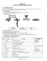
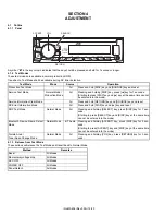
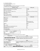
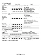
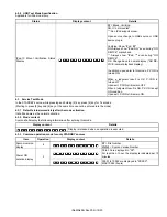
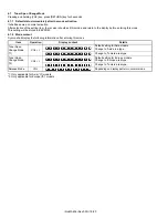
In order to prevent serious damage on the circuit, fuse pattern is prepared on the GND line of RCA Terminal. This damage may
take due to improper part replacement with a external equipment via RCA line.
2.1.2 Repair Procedure
(1) Check the shorted circuit at the meltdown point.
Need to clean up if the shorted circuit or carbonization happen at the fuse pattern.
(2) Add following part on the fuse pattern.
(3) Check output level.
2.1.3 After finished repair
Due to improper part replacement, this meltdown occurs.
Thus please notice following information when the unit is returned to your customer.
Things to be checked before installing the unit.
(1) Check the GND line of external amplifier or other equipment which must connect properly.
(2) Check whether the GND line is not short-circuited with the battery terminal. (do not short-circuit these lines)
2.2
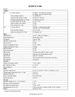
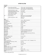
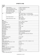
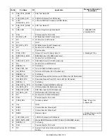
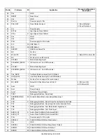
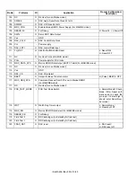
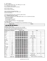
MICROCOMPUTER’S TERMINAL DESCRIPTION
IC701 (R5S726A0D216FP) on MAIN PWB ASSY
Part Number
Part Name
SPEC
F53-0513-08
PATTERN FUSE
4A
Pin No.
Pin Name
I/O
Application
Processing/Operation/
Description
1
LCD_INH
O Display On/Off Control
L: Display OFF/
H: Display ON
2
DAB_COM_ON
O Enable DAB micon (For DAB model)
H: ON/L: OFF
2
NC
O No Use (for non DAB model)
3
PVcc
-
Power supply for I/O circuits
4
DZF
I
Zero Input Detect
L: Mute OFF/H: Mute ON
5
Vss
-
GND
6
PANEL_PON
O Supply Control to Panel
L: ON/H: OFF
7
DC_ERR2
I
Detect DC Clip (for ST Power Amp IC)
L: DC Error ON/
H: DC Error OFF
8
PWIC_MUTE
O Muting Output for Power Amp IC
L: Mute ON/H: Mute OFF
9
LCD_CE
O LCD Driver IC Chip Enable Output (for LCD Model)
10
Vss
-
GND
11
LCD_CLK
O LCD CLK Output
12
Vcc
-
Power supply
13
RGB_CLK
O I2C Clock Output for RGB Driver (For RGB Model)
Meltdown point


