


KD-DV6206/KD-DV6205
Installation/Connection Manual
GET0383-007A
[A]
0306DTSMDTJEIN
EN
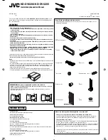
Parts list for installation and connection
The following parts are provided for this unit. If any item is missing, consult your JVC car
audio dealer immediately.
This unit is designed to operate on
12 V DC, NEGATIVE ground electrical systems
. If your
vehicle does not have this system, a voltage inverter is required, which can be purchased at
JVC car audio dealers.
WARNINGS
• DO NOT install any unit in locations where;
– it may obstruct the steering wheel and gearshift lever operations, as this may result in
a traffic accident.
– it may obstruct the operation of safety devices such as air bags, as this may result in
a fatal accident.
– it may obstruct visibility.
• DO NOT operate any unit while manipulating the steering wheel, as this may result in a
traffic accident.
• The driver must not watch the monitor while driving.
If the driver watches the monitor while driving, it may lead to carelessness and cause
an accident.
• The driver must not put on the headphones while driving. It is dangerous to shut off the
outside sounds while driving.
• If you need to operate the unit while driving, be sure to look ahead carefully or you may
be involved in a traffic accident.
• If the parking brake is not engaged, “DRIVER MUST NOT WATCH THE MONITOR WHILE
DRIVING.” appears on the monitor, and no playback picture will be shown.
– This warning appears only when the parking brake wire is connected to the parking
brake system built in the car.
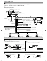
To prevent short circuits, we recommend that you disconnect the battery’s negative terminal and
make all electrical connections before installing the unit.
•
Be sure to ground this unit to the car’s chassis again after installation.
Notes:
• Replace the fuse with one of the specified rating. If the fuse blows frequently, consult your JVC
car audio dealer.
• It is recommended to connect to the speakers with maximum power of more than 50 W (both
at the rear and at the front, with an impedance of
4
Ω
to 8
Ω
). If the maximum power is less
than 50 W, change “AMP GAIN” setting to prevent the speakers from being damaged (see
page 36 of the INSTRUCTIONS).
• To prevent short-circuit, cover the terminals of the UNUSED leads with insulating tape.
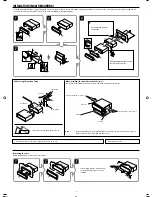
• The heat sink becomes very hot after use. Be careful not to touch it when removing this unit.
1
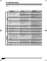
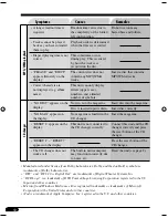
TROUBLESHOOTING
•
The fuse blows.
* Are the red and black leads connected correctly?
•
Power cannot be turned on.
* Is the yellow lead connected?
•
No sound from the speakers.
* Is the speaker output lead short-circuited?
•
Sound is distorted.
* Is the speaker output lead grounded?
* Are the “–” terminals of L and R speakers grounded in common?
•
Noise interfere with sounds.
* Is the rear ground terminal connected to the car’s chassis using shorter and thicker cords?
•
The unit becomes hot.
* Is the speaker output lead grounded?
* Are the “–” terminals of L and R speakers grounded in common?
•
This unit does not work at all.
* Have you reset your unit?
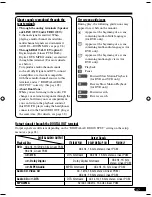
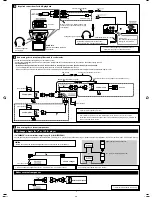
About sounds reproduced through the rear terminals
•
Through the analog terminals (Speaker out/LINE OUT/2nd AUDIO OUT):
2-channel signal is emitted. When playing a multi-channel encoded disc, multi-channel
signals are downmixed. (AUDIO—DOWN MIX: see page 28 of the INSTRUCTIONS.)
• Through DIGITAL OUT (optical):
Digital signals (Linear PCM, Dolby Digital*
1
, DTS*
2
, MPEG Audio) are emitted through this
terminal. (For more details, see page 47 of the INSTRUCTIONS.)
To reproduce multi-channel sounds such as Dolby Digital and DTS, connect an amplifier or
a decoder compatible with these multi-channel sources to this terminal, and set “DIGITAL
AUDIO OUTPUT” correctly. (See page 28 of the INSTRUCTIONS.)
*
1
Manufactured under license from Dolby Laboratories. Dolby and the double-D symbol are trademarks
of Dolby Laboratories.
*
2
“DTS” and “DTS 2.0 + Digital Out” are trademarks of Digital Theater Systems, Inc.
© 2006 Victor Company of Japan, Limited
PRECAUTIONS on power supply and speaker connections:
•
DO NOT connect the speaker leads of the power cord to the car battery; otherwise,
the unit will be seriously damaged.
• BEFORE connecting the speaker leads of the power cord to the speakers, check the
speaker wiring in your car.
Heat sink
F
Crimp connector
K
Handles
G
Washer (ø5)
H
Lock nut (M5)
I
Mounting bolt (M5
×
20 mm)
J
Rubber cushion
A
/
B
Hard case/Control panel
C
Sleeve
D
Trim plate
E
Power cord
L
Remote controller
M
Battery
Instal1-2_DV6206_007A_1.indd 1
Instal1-2_DV6206_007A_1.indd 1
2/7/06 12:10:34 PM
2/7/06 12:10:34 PM


