


28
Set to TRIG or
SPLIT
LCD screen
LAN card display
e
No LAN card is inserted when the
display
appears on. Turn off the power and insert a LAN
card. Then, turn the power back on.
NETWORK PACK CONFIG
menu screen
ENCODE SET menu screen
NE T WOR K
T . .
. .
. .
S E
OR
T W
E
N
K
A CK
P
ON
C
I G
F
E N CO DE S E T
MPE G R EC
T R G
I
MOV I E CL I P S E T
MENU R E S E T
PAGE B ACK
LAN card
Sending playback signals of a DV cassette tape using a LAN card
1.
Insert a LAN card into the Network Pack.
2.
Turn on the GY-DV300 power.
Check to see that the LAN card display is showing on the LCD screen/viewfinder
screen.
3.
Set the MODE switch to “VTR”.
4.
Insert the recorded DV cassette tape.
5.
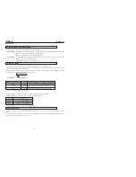
Set the NETWORK PACK CONFIG menu screen.
q
Set MPEG REC to “SPLIT”.
w
Set the video/audio compression in the ENCODE SET menu screen.
(
☞
page 6)
e
When completed with settings, press the MENU button to return to the normal
screen.
6.
Launch Streamproducer.*
7.
Press the BAR (
t
/
w
) button of GY-DV300 to start DV cassette tape playback.
8.
Press the SELECT dial at the beginning of the scene to send from LAN
card.
●
Start transmission. The LAN card display on the LCD screen/viewfinder screen
will be as follows:
e
: Yellow display during data transmission.
Displayed in red when the media operating Streamproducer* at the des-
tination of transmission starts recording.
* Perform setting described in “5-2 Operating video from DV camcorder • Trigger
mode function” of network distribution software “Streamproducer” User’s Guide.
9.
To stop transmission, press the SELECT dial.
10
.
To resume transmission, press the SELECT dial once more.
11
.
To end, stop transmission and turn off the power. Lastly, remove the LAN memory
card.
POWER
OFF
ON
MODE
CAM-B
VTR
SHUTTER
MENU
GAIN
CAM-A
BAR
AW
FWD
REV
POWER switch
MODE switch
MENU
button
SELECT
Tdial
<GY-DV300 rear panel>
29
NETWORK PACK SETUP
Controlling GY-DU300/KA-DU300 via a LAN card
With the Network Pack, GY-DV300/KA-DV300 can be controlled via LAN.
It is also possible to playback video and audio from KA-DV300 on your PC in the STREAMCAPTURE screen in realtime (live display) as
well as save data to files. However, note that video and audio from KA-DV300 can be played back only on one PC at a time.
Peer-to-peer connection that directly connects the unit with a PC is explained here.
PROFESSINAL
DV CAMCORDER GY-DV300
IRIS
AUDIO
LEVEL
CH-1
CH-2
ND FILTER
ON
OFF
FOCUS
AUTO
PUSH
AUTO
MANU
OPEN
GY-DV300
Set the LAN card driver by
following the instructions on
manual provided by the card
manufacturer.
KA-DV300
10 BASE-T
cross cable
Socket Com: EA2900-117 (USA)
EA2903-162 (Europe)
EA2906-194 (Asia)
(CF memory card adapter (PCMCIA TYPE I/II
specifications)(sold separately) is required for
inserting this card.)
1.
Turn your PC and GY-DV300 power off.
2.
Insert the PCMCIA LAN card to specify into KA-DV300.
3.
Connect the unit and PC using a 10 BASE-T cross cable.
4.
Turn the PC and GY-DV300 power on.
5.
Insert a recordable DV cassette tape.
6.
PC settings
●
Set the LAN card driver according to the manual provided
by the card manufacturer.
●
Network settings (
☞
page 13)
q
Set the following items in the TCP IP properties:
* DHCP server is not used.
IP address: 192.168.100.105
Subnet mask: 255.255.255.000
w
Setting the proxy server.
• Set the proxy server using the “LAN SETTINGS” of
Windows.
• When using peer-to-peer communication that directly
connects the PC and KA-DV300, deselect the “Use a
proxy server” checkbox.
• When the “Use a proxy server” setting must be en-
abled due to a LAN environment (in-company LAN,
etc.), click “Advanced...” and input the IP address of
GY-DV300 in “Exceptions” of the “Use a proxy server”
setting.
(
☞
“About proxy servers,” Page 41)
7.
Launch the browser on your PC and enter 192.168.100.101
(default factory setting) in the address bar and press ENTER.
●
A confirmation window for user ID and password appears.
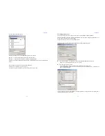
8.
Input the user ID and password.
q
For the user ID, input “jvc” (factory setting).
For the password, input “ka-dv300” (factory setting) or the
name set in the NETWORK SET [2/2] menu screen.
(
☞
page 10)
w
Check to make sure the inputted user ID and password
are correct and click the OK icon.
(Check “Save password” so that the password does not
need to be inputted for future accesses.)
9.
If the user ID and password are correct, the NETWORK PACK
SETUP screen appears on the PC monitor.
●
GY-DV300/KA-DV300 settings and operations can be con-
trolled using the NETWORK PACK SETUP. (
☞
page 30)
PC
?
X
OK
Cancel
Enter Network Password
Please enter tour authentication information.
Resource
secured
User name:
Password:
Caution
●
When setting the NETWORK PACK SETUP screen (CAM-
ERA CONTROL, NETWORK SETUP, PORT SETUP or EN-
CODE PARAMETERS) and the same menu screen is dis-
played on the LCD screen or viewfinder of GY-DV300, val-
ues set in the NETWORK PACK SETUP screen will not ap-
pear on menu screen of the LCD screen or the viewfinder of
GY-DV300.
The values set in the NETWORK PACK SETUP screen will
appear after the menu screen of GY-DV300 is closed once
and reopened.
●
During camera/VTR control, noise may be heard from the
speakers. However, this is not a malfunction. If the noise
becomes irritating, open the “Sound & Multimedia” property
from the Windows Control Panel and set the sound of “Win-
dows Explorer Start Navigation” of “Sound Events” to off.
* For setting details, see Windows’ Help.