
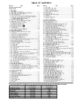


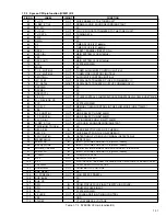


1-2
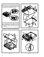
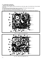
Fig. D1
Fig. D3
Fig. D2
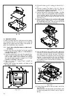
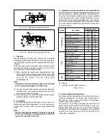
Fig. 1
Fig. 2
Fig. 3
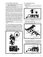
1
(S1a)
(S1a)
(S1a)
(S1b)
1
(S1c)
(S1c)
Bracket
Top cover
Procedures for Lowering the Cassette holder assembly
2
(S2a)
Earth plate
<Note 2>
(S2b)
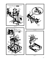
(L2a)
(L2a)
(L2b)
(L3)
(L3)
CN901
WR3a
Foil side
<Note 3a>
3
(L3)
a <Note 3b>
Jog shuttle
WR3b
Foil side
<Note 3a>
CN3012
[HR-S7700MS]
CN7002
[HR-S6700MS]
CN7192
Front panel
back side
Jack board
assembly
WR3a
(S3)
Turn the loading motor pulley in the direction as indicated by
Fig.2. As both
Å
and
ı
levers are lodged twice, push the
levers in the direction as indicated by Fig.3 to release them.
When pushing the levers, do it in the order of
Å
,
ı
,
ı
,
Å
.
When the holder has been lowered, turn the pulley until the
cassette holder is securely in place without allowing any up/
down movement.
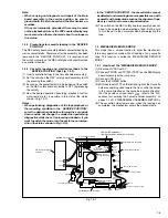
Procedures for Lowering the Cassette holder assembly
As the mechanism of this unit is integrated with the Housing
assembly, the holder must be lowered and the two screws un-
screwed when removing the Mechanism assembly.
Summary of Contents for HR-S6700MS
Page 5: ......


