

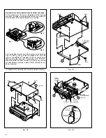

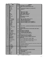


1-5
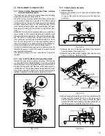
1.4.2 Precautions for cassette loading in the "SERVICE
POSITION"
The REC safety board assembly detects cassette loading as
well as cassette tabs. Therefore, after the assembly has been
removed in the "SERVICE POSITION", it is required to set
the switch manually on the REC safety board assembly when
a cassette is loaded.
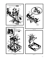
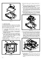
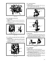
1.4.3 Cassette loading and ejection methods in the
“SERVICE POSITION”(See Fig. 1-4-3).
(1) Insert a cassette halfway in the Cassette holder assembly.
(2) Set the switch on the REC safety board assembly to ON
(by pressing the switch).
(3) As soon as the cassette starts to be loaded, set the switch
on the REC safety board assembly to OFF (by releasing
the switch).
(4) Now the desired operation (recording, playback, fast for-
ward, rewind, etc.) is possible in this status (the status
shown in Fig.1-4-3).
Notes:
• When performing diagnostics of the tape playback or
the recording condition in the "SERVICE POSITION",
enter the desired mode before turning the set upside
down, and do not change the mode when performing
diagnostics while the set is placed upside down. If you
want to switch the mode, turn the set to the normal po-
sition (the status shown in Fig.1-4-3).
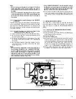
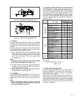
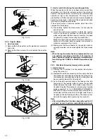
1.5 MECHANISM SERVICE MODE
This model has a unique function to enter the mechanism
into every operation mode without loading of any cassette
tape. This function is called the “MECHANISM SERVICE
MODE”.
1.5.1 How to set the "MECHANISM SERVICE MODE"
(1) Disconnect VCR from AC.
(2) Connect TPGND and TP7001 (TEST) on the SW/Display
board assembly with a jump wire.
(3) Connect VCR to AC.
(4) Press the POWER button.
(5) With lock levers
Åı
on the left and right of the Cassette
holder assembly pulled toward the front, slide the holder
in the same direction as the cassette insertion direction.
(For the positions of lock levers
Åı
, refer to the “Pro-
cedures for Lowering the Cassette holder assembly” on
pages 1-2 of 1.3 DISASSEMBLY/ASSEMBLY METHOD.)
(6) The cassette holder lowers and, when the loading has
completed, the mechanism enters the desired mode.
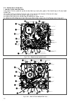
Fig. 1-5-1
Jack board assembly
CP4001
CP5302
CN513
Main board assembly
2D Digital [HR-S6700MS] or
3D Digital/2M [HR-S7700MS] board assembly
S-Sub board assembly
DEMOD board assembly
P/S Converter board
assembly
Audio erase
board assembly
Terminal board assembly
TP111
D.FF
TP4001
CTL.P
TP2253
A.FM
TP106
PB.FM
CN902
CN901
CN6102
CN7192
CN3502
CN3501
CN7191
CN7001
CN7002
[HR-S6700MS]
To Shuttle play [HR-S6700MS]
REC safety board
assembly
SW/Display board assembly
CP5301
VR1401
D/A LEVEL ADJ
[HR-S7700MS]
CN3011
CN3012 [HR-S7700MS]
To Jog
[HR-S7700MS]
TPGND
TP7001 (TEST)
Note:
• When carrying out diagnosis and repair of the Main
board assembly in the service position, be sure to
ground both the Main board and the Mechanism as-
semblies.
If they are improperly grounded, there may be noise
on the playback picture or the FDP counter display may
move even when the mechanism is kept in an inopera-
tive status.
• In the "SERVICE POSITION", the cassette tabs cannot
be detected and recording becomes possible even with
a cassette with broken tabs such as the alignment tape.
Be very careful not to erase important tapes.
(5) The switch on the REC safety board assembly does not
have to be operated when ejecting a tape. But be sure
to turn the set to the normal position before ejecting the
tape.
Summary of Contents for HR-S6700MS
Page 5: ......


