


2-11
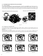
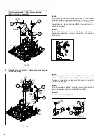
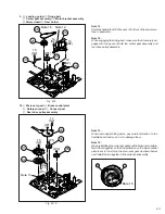
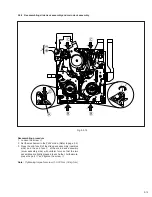
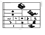
Fig. M9
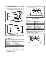
9.
t
Loading guide/
y
Timing belt
u
Center gear assembly/
i
Motor bracket assembly
o
Worm wheel/
p
Gear holder
Note 12:
Carefully handle the DEW sensor. (Don’t touch the sensor sur-
face in particular.)
Note 16:
When engaging the timing belt, make sure that it securely en-
gages with the gears of both the center gear assembly and
reel drive pulley assembly.
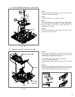
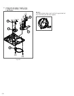
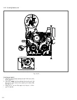
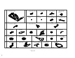
Fig. M10
10.
Q
Main cam gear/
W
Brake control plate
E
Rotary encoder/
R
Connect gear
T
Reel drive pulley assembly
Note 13:
When removing/refitting parts, pay careful attention to the
flexible board and so on not to damage them.
Note 15:
When reinstalling the main cam gear and the brake control plate,
first fit them together so that the protrusion on the brake control
plate is set in the slot on the main cam gear as shown below,
next install the two together to the main deck assembly.
30
(W1)
15
(S2)
14
(S2)
Note 12
Note 16
13
(S2)
12
(S2)
27
26
28
29
25
31
(W1)
(W1)
17
(S2)
16
(S2)
Note
15
Note 13
(L15)
(W2)
32
33
34
35
Note 15
31
32