
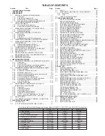


1-6
5
D
B
G
H
E
C
LUG WIRE
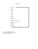
MONITOR
ASSY
NOTE9
NOTE9
17
(S1)
LUG WIRE
LUG WIRE
NOTE10
CAP (REAR JACK)
20
(S1)
19
(S1)
NOTE11
18
(S4)
17
(S1)
F
✽
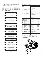
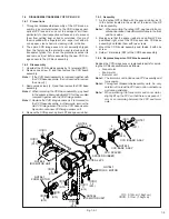
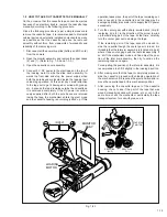
Fig. 1-3-6
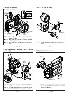
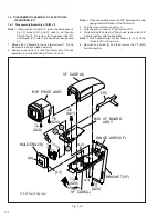
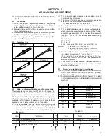
6
Front cover assembly (including
7
MIC /
8
DC light
assembly)
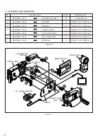
Fig. 1-3-8
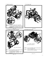
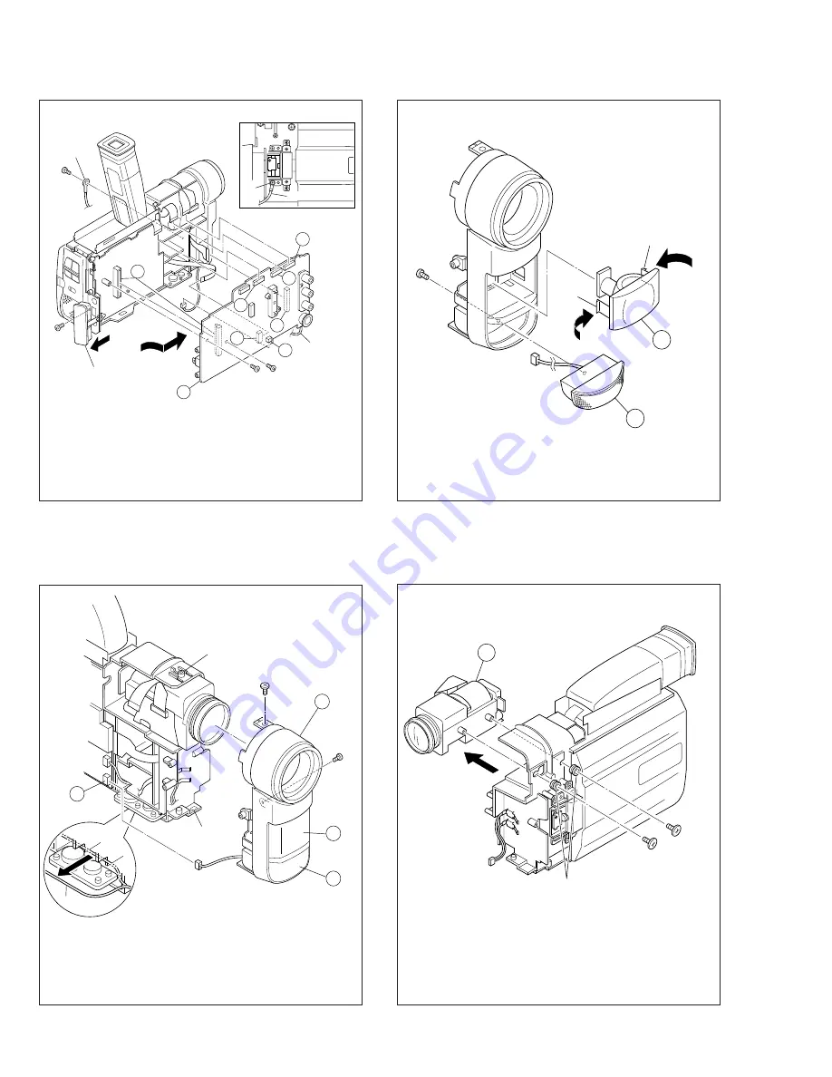
Fig. 1-3-9
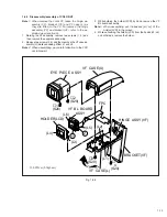
5
MAIN board assembly
7
MIC /
8
DC light assembly
9
OP (optical) block assembly
Fig. 1-3-7
✽
: 0.07N·m (0.7kgf·cm)
Note
9:
Remove the lug wire fastened together with the
bracket (monitor).
Note
10: Remove the cap (rear jack) before proceeding to
the removing work.
Note
11: DC light assembly (in the GR-DVF21U/DVF31U
only).
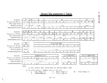
21
(S1)
22
(S5)
(L8)
8
6
7
(L9)
NOTE12
WIRE(MIC)
NOTE11
J
23
(S1)
(L10)
(L11)
8
7
NOTE 11
9
25
(S6)
24
(S6)
CUSHION(OP)
NOTE 13
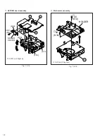
Note
13: For disassembling the OP block Assembly, refer
to "1-4 DISASSEMBLY/ASSEMBLY OF OP
BLOCK ASSEMBLY"
Note
11: DC light assembly (in the GR-DVF21U/DVF31U
only).
Note
12: When reassembling, set the microphone wire in
the groove (gap) between the frame and base.
Note
11: DC light assembly (in the GR-DVF21U/DVF31U
only).