


2-1
3
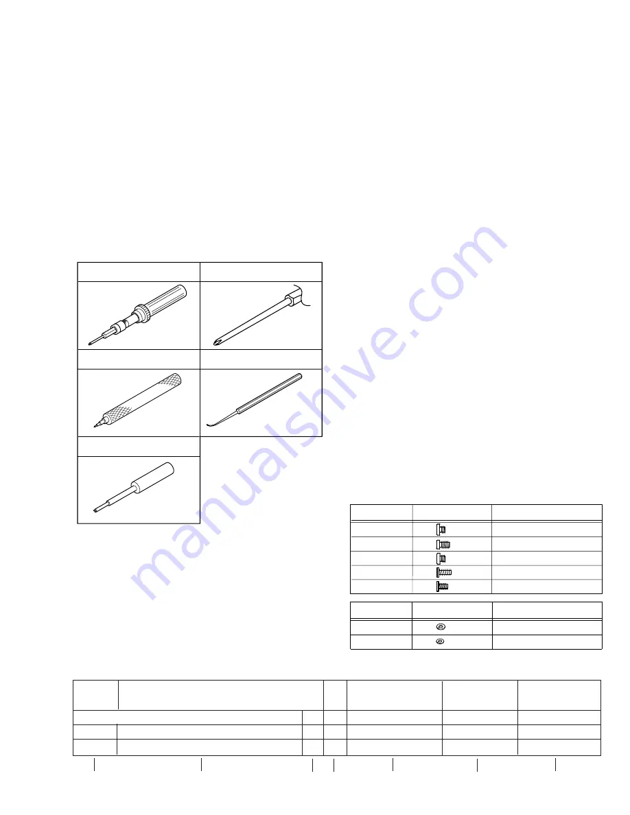
Bit
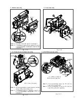
YTU94088-003
1
2
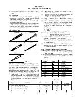
Torque driver
YTU94088
Slit washer fitting jig
YTU94121A
5
4
Chip IC replacement jig
PTS40844-2
Guide driver
YTU94148A
A
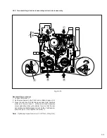
Cassette housing assembly
T
M1
3(S1),(L1)-(L4)
1,28,29,30
Adjustment
1
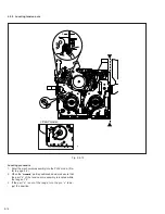
Reel disk (SUP) assembly
T
M2
(W1)
2,3
2
Reel disk (TU) assembly
T
M2
(W1)
2,3
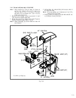
SECTION 2
MECHANISM ADJUSTMENT
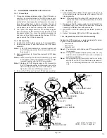
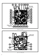
Fig. 2-1-1
2.1 PRELIMINARY REMARKS ON ADJUSTMENT AND RE-
PAIR
2.1.1 Precautions
1. When fastening parts, pay careful attention to the tightening
torque of each screw. Unless otherwise specified, tighten a
screw with the torque of 0.04 N·m (0.4 kgf·cm).
2. Be sure to disconnect the set from the power supply before fas-
tening and soldering parts.
3. When disconnecting/connecting wires, be careful not to get them
and their connectors damaged. (Refer to the Section 1.)
4. When replacing parts, be very careful neither to damage other
parts nor to fit wrong parts by mistake.
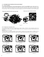
2.1.2 Necessary jigs
Table 2-1-1
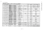
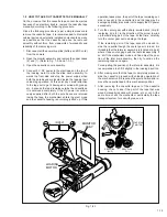
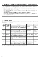
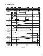
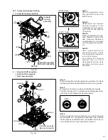
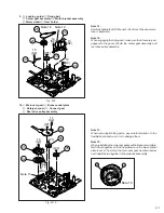
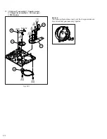
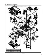
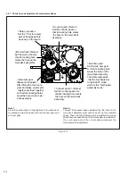
2.1.3 Notes on disassembling/reassembling procedure
The disassembling procedure table (Table 2-2-2 on page 2-5,
a part of the table is shown below for reference) shows the
procedure to disassemble/reassemble mechanism parts.
Carefully read the following explanation before starting actual
disassembling/reassembling work. The item numbers (circled
numbers) in the following explanation correspond to those
appearing under respective columns of the table.
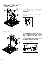
(1)
Circled numbers appearing in this column indicate the
order to remove parts. When reassembling, follow these
numbers in the reverse order. Circled numbers in this
column correspond to those appearing in drawings of
this section.
(2)
This column shows part names corresponding to circled
numbers in the left column.
(3)
The symbol (T or B) appearing in this column shows the
side which the objective part is mounted on.
T = the upper side, B = the lower side
(4)
Symbols appearing in this column indicate drawing
numbers.
(5)
This column indicates parts and points such as screws,
washers, springs, and others to be removed/fitted for dis-
assembling/reassembling the mechanism. Besides such
the parts, this column occasionally indicates working
points.
P = Spring
W = Washer
S = Screw
Lock (L), soldering (SD), shield, connector (CN), etc.
Example
• Remove (W1) = Washer W1.
• Remove the solder at (SD1) = Point SD1.
• Disconnect
A
= Connector
A
.
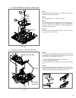
(6)
Numbers in this column represent the numbers of notes
in the text. For example, “1” means “Note 1”.
( F o r p a r t s t h a t n e e d p h a s e a d j u s t m e n t a f t e r re-
assembling, refer to “2.2.7 Check and adjustment of
mechanism phase”.)
(7)
This column indicates required after-disassembling/-
reassembling work such as phase adjustment or
mechanism adjustment.
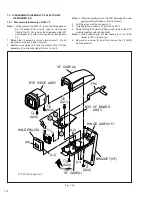
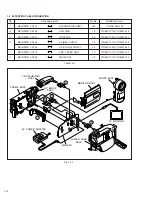
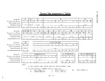
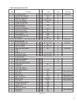
2.1.4 Screws and washers used in mechanism
Table 2-1-1 shows screws and washers used in the mechanism
by the part numbers with their respective symbols,
shapes and colors.
When disassembling/reassembling the mechanism, be careful
not to make any mistake in removing/refitting screws and
washers.
Step
Part Name
Fig.
W1
W2
YQ44246
YQ44246-2
Shape
Parts No.
Symbol
Shape
Parts No.
Symbol
(S1)
(S2)
(S3)
(S5)
YQ43893-4
YQ43893-2
YQ43893
QYSLSP2030D
(S4)
QYSLSF2055D
Point
Note
Remoarks
(1)
(2)
(3)
(4)
(5)
(6)
(7)
5
5
5
5
5
5
5