background image

EN

33

7

4

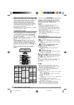
DUBBING

Dubbing To Or From A VCR

To Use This Camcorder As A Player

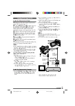
1

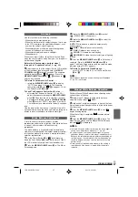
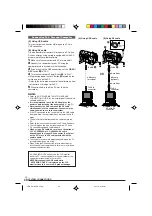
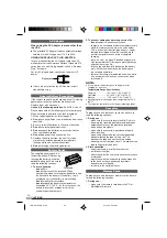
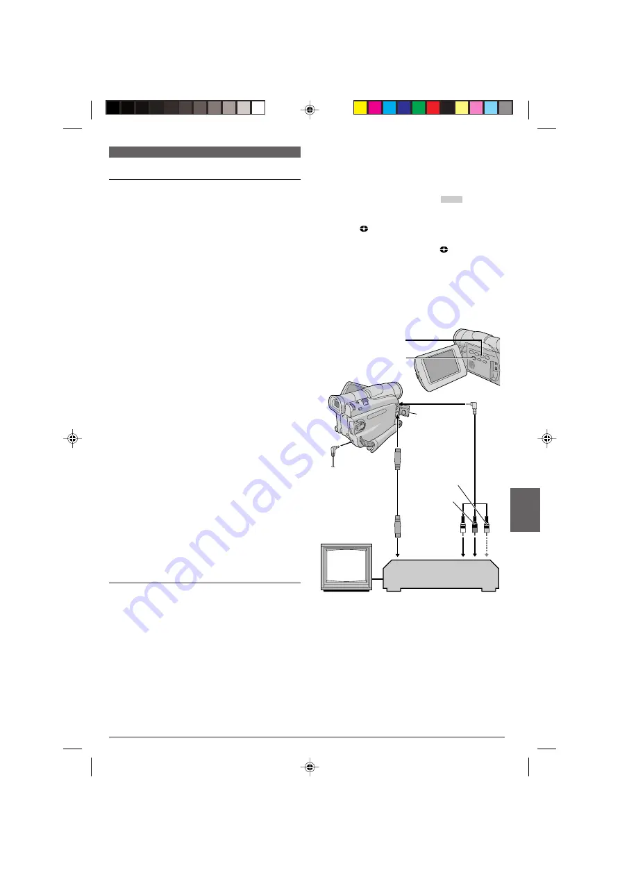
Following the illustration, connect the camcorder

and the VCR. Also refer to pg. 16.

2

Set the 

VIDEO/DSC

 Switch 

4

 to “VIDEO”, then set

the camcorder’s Power Switch 

u

 to “PLAY” while

pressing down the Lock Button 

y

 located on the

switch, turn on the VCR’s power, and insert the
appropriate cassettes in the camcorder and the VCR.

3

Engage the VCR’s AUX and Record-Pause modes.

4

Engage the camcorder’s Play mode to find a spot

just before the edit-in point. Once it is reached, press

4

/

6


7

 on the camcorder.

5

Press 

4

/

6


7

 on the camcorder and engage the

VCR’s Record mode.

6

Engage the VCR’s Record-Pause mode and press

4

/

6


7

 on the camcorder.

7

Repeat steps 

4

 through 

6

 for additional editing, then

stop the VCR and camcorder when finished.

NOTES:

As the camcorder starts to play your footage it will appear
on your TV. This will confirm the connections and the AUX
channel for dubbing purposes.

Before you start dubbing, make sure that the indications
do not appear on the connected TV. If they do, they are
being recorded onto the new tape.

To choose whether or not the following displays
appear on the connected TV . . .

• Date/Time

..... set “DATE/TIME” to “AUTO”, “ON” or “OFF” in the

Menu Screen (

 pg. 30, 32).

Or, press 

DISPLAY


U

 on the remote control to

turn on/off the date indication.

• Time Code

..... set “TIME CODE” to “ON” or “OFF” in the Menu

Screen (

 pg. 31, 32).

• Indications other than date/time and time code

..... set “ON SCREEN” to “LCD”, “LCD/TV” or “OFF” in

the Menu Screen (

 pg. 30, 32).

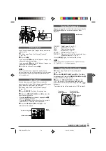
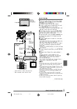
Connector
cover

*

* When connecting the cables, open this cover.
** Connect when an S-Video cable is not used.

VCR

TV

To AV 

(

To
S-VIDEO 

q

Audio/
Video cable
(provided)

White to
AUDIO L
IN or OUT

Red to AUDIO
R IN or OUT

To S-VIDEO
IN or OUT

S-Video cable
(optional)

Yellow to VIDEO

**

IN or OUT

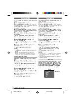
2.

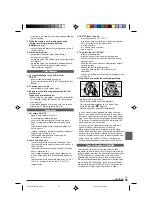
Set “S/AV INPUT” to “ON” and set “REC MODE” to
“SP” or “LP” (

 pg. 31).

3.

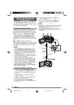
Connect the cables as shown in the illustration and
load a cassette to record on.

4.

Press the Recording Start/Stop button 

e

 to

engage the Record-Pause mode. “

AV. IN

” appears

on the screen.

5.

Press the Recording Start/Stop button 

e

 to start

recording. 


3

 rotates.

6.

Press the Recording Start/Stop button 

e

 again to

engage the Record-Pause mode. 


3

 stops

rotating.

NOTES:

After dubbing, set “S/AV INPUT” back to “OFF”.

Analog signals can be converted to digital signals with
this procedure.

It is also possible to dub from another camcorder.

To Use This Camcorder As A Recorder

1.

Set the 

VIDEO/DSC

 Switch 

4

 to “VIDEO”, then set

the camcorder’s Power Switch 

u

 to “PLAY” while

pressing down the Lock Button 

y

 located on the

switch.

  1 GR-D91US EN 23-34

02.11.6, 2:15 PM

33

Summary of Contents for GR-D91

Page 1: ...del No and Serial No which is located on the bottom of the camcorder Retain this information for future reference Model No Serial No INSTRUCTIONS GR D91 DIGITAL VIDEO CAMERA EN LYT1072 001B ENGLISH CONTENTS AUTOMATIC DEMONSTRATION 6 GETTING STARTED 7 11 TAPE RECORDING PLAYBACK 12 16 MEMORY CARD RECORDING PLAYBACK 17 22 ADVANCED FEATURES 23 40 REFERENCES 41 55 1 GR D91US EN 01 11_Malaysia 02 11 21 ...

Page 2: ...HOOTING 41 43 CAUTIONS 44 46 SPECIFICATIONS 47 INDEX 48 53 Controls Connectors And Indicators 48 49 Indications 50 53 TERMS 54 55 Refer to the diagrams on page 48 and 50 while reading the instruction manual as all the controls connectors indicators and indications are numbered on the diagrams and those corresponding numbers are used throughout this manual unless specified GETTING STARTED Power 7 8...

Page 3: ...ces such as lighted candles should be placed on the apparatus When discarding batteries environmental problems must be considered and the local rules or laws governing the disposal of these batteries must be followed strictly The apparatus shall not be exposed to dripping or splashing Do not use this equipment in a bathroom or places with water Also do not place any containers filled with water or...

Page 4: ...od on unsteady or unlevel surfaces It could tip over causing serious damage to the camcorder CAUTION Connecting cables Audio Video S Video etc to the camcorder and leaving the unit on top of the TV is not recommended as tripping on the cables will cause the camcorder to fall resulting in damage 䡲 This camcorder is designed exclusively for the digital video cassette SD Memory Card and MultiMediaCar...

Page 5: ... Pack BN V408U AC Adapter AP V11U or AP V13U Lens Cap See below for attachment or PROVIDED ACCESSORIES None CD ROM Editing Cable Remote Control Unit RM V717U AAA R03 Battery x 2 for remote control unit 1 2 3 Tab Core Filter for optional S Video cable 墌 pg 6 for attachment To protect the lens attach the provided lens cap to the camcorder as shown in the illustration NOTE To confirm the lens cap is ...

Page 6: ... MENU VOLUME wheel to select OFF and press it 5 Rotate the MENU VOLUME wheel to select RETURN and press it twice The normal screen appears NOTE If you do not detach the Lens Cap you cannot see the actual changes of the Automatic Demonstration activated on the LCD monitor or viewfinder AUTOMATIC DEMONSTRATION None RETURN OFF ON EMO MODE D S Y S TEM u y Sub Menu Attach the Core Filter s if provided ...

Page 7: ...ection in the AC range from 110 V to 240 V GETTING STARTED Battery pack To DC connector To AC outlet AC Adapter ATTENTION Before detaching the power source make sure that the camcorder s power is turned off Failure to do so can result in a camcorder malfunction INFORMATION The extended use battery pack kit is a set composed of a battery pack and AC Power Adapter Charger VU V840 KIT BN V840U batter...

Page 8: ...or a short time then re attach it to the camcorder As long as the battery pack itself is not cold it should not affect performance If you re using a heating pad make sure the battery pack does not come in direct contact with it Since the AC Adapter processes electricity internally it becomes warm during use Be sure to use it only in well ventilated areas The following operation stops charging Set ...

Page 9: ...e a tape and press PUSH HERE to close the cassette holder Once the cassette holder is closed it recedes automatically Wait until it recedes completely before closing the cassette holder cover When the battery s charge is low you may not be able to close the cassette holder cover Do not apply force Replace the battery with a fully charged one before continuing 3 Close the cassette holder cover firm...

Page 10: ... the MENU VOLUME wheel to select CAMERA DISPLAY and press it 4 Rotate the MENU VOLUME wheel to select CLOCK ADJ Press it and month is highlighted Rotate the MENU VOLUME wheel to input the month Press it Repeat to input the day year hour and minute Rotate the MENU VOLUME wheel to select RETURN and press it twice The Menu Screen closes NOTE Even if you select CLOCK ADJ if the parameter is not highli...

Page 11: ...ect DSC and press it 4 Rotate the MENU VOLUME wheel to select QUALITY and press it The Sub Menu appears Rotate the MENU VOLUME wheel to select the desired mode and press it 5 Rotate the MENU VOLUME wheel to select IMAGE SIZE and press it The Sub Menu appears Rotate the MENU VOLUME wheel to select the desired mode and press it 6 Rotate the MENU VOLUME wheel to select RETURN and press it twice The M...

Page 12: ...VOLUME wheel again so that the bright level indicator t disap pears 4 Rotate the MENU VOLUME wheel until the bright level indicator moves and the appropriate brightness is reached then press it The bright level indicator t disappears It is also possible to adjust the brightness of the viewfinder by closing the LCD monitor pulling out the viewfinder and adjusting as described above TAPE RECORDING N...

Page 13: ...o that it faces forward then point the lens toward yourself and start recording Operation Mode Choose the appropriate operation mode according to your preference using the Power Switch u and VIDEO DSC Switch 4 Zooming To produce the zoom in out effect or an instantaneous change in image magnification Zoom In Slide the Power Zoom Lever towards T Zoom Out Slide the Power Zoom Lever towards W 䡲 The f...

Page 14: ...g 14 Normal Playback 2 Set the Power Switch u to or while pressing down the Lock Button y located on the switch then start recording NOTES The time code cannot be reset During fast forwarding and rewinding the time code indication does not move smoothly The time code is displayed only when TIME CODE is set to ON 墌 pg 31 Frames 30 frames 1 second Seconds Minutes Frames are not displayed during reco...

Page 15: ... shorter than 5 seconds of tape may not be detected The detected blank portion may be located between recorded scenes Before you start recording make sure there is no recorded scene after the blank portion NOTES If Stop mode continues for 5 minutes when power is supplied from a battery the camcorder shuts off automatically To turn on again set the Power Switch u to OFF CHARGE then to PLAY The play...

Page 16: ... to AUTO ON or OFF in the Menu Screen 墌 pg 30 32 Or press DISPLAY U on the remote control to turn on off the date indication Time Code set TIME CODE to ON or OFF in the Menu Screen 墌 pg 31 32 Indications other than date time and time code set ON SCREEN to LCD LCD TV or OFF in the Menu Screen 墌 pg 30 32 NOTES It is recommended to use the AC Adapter as the power supply instead of the battery pack 墌 ...

Page 17: ...s not possible PHOTO y blinks when SNAPSHOT is pressed If Program AE with special effects 墌 pg 23 is engaged certain modes of Program AE with special effects are disabled during Snapshot recording In such a case the icon blinks If shooting is not performed for approx 5 minutes when the Power Switch u is set to or and power is supplied from the battery pack the camcorder shuts off automatically to ...

Page 18: ...Screen Display Images shot in a file size that is not compatible with this camcorder will be displayed as reduced size thumbnail images These thumbnail images cannot be transferred to a PC Images shot with devices such as JVC GR DVM70 that are not compatible with DCF cannot be viewed with this camcorder UNSUPPORTED FILE will be displayed Approximate Number of Storable Images Provided Optional NOTE...

Page 19: ...n 4 Press the MENU VOLUME wheel in The selected file is displayed Index Screen Viewing File Information You can get the relevant file information by pressing the INFO button 0 during normal playback or Index playback FOLDER Folder name 墌 pg 22 FILE File name 墌 pg 22 DATE Date the file was made SIZE Image size 墌 pg 11 QUALITY Picture quality 墌 pg 11 PROTECT When set to ON the file is protected from...

Page 20: ... selected CURRENT press 2 6 or 3 8 to select the desired file 6 Rotate the MENU VOLUME wheel to select EXECUTE and press it To cancel selection select RETURN ADVANCED FEATURES Deleting Files Previously stored files can be deleted either one at a time or all at once 1 Load a memory card 墌 pg 11 2 Set the VIDEO DSC Switch 4 to DSC then set the Power Switch u to PLAY while pressing down the Lock Butt...

Page 21: ...the DPOF Digital Print Order Format standard in order to support future systems such as automatic printing which records information about the still images you wish to print such as the number of prints to make There are 2 print information settings available TO PRINT ALL STILL IMAGES ONE PRINT FOR EACH explained below and TO PRINT BY SELECTING STILL IMAGES AND NO OF PRINTS TO PRINT ALL STILL IMAG...

Page 22: ...s by rotating the MENU VOLUME wheel and press it Repeat steps 3 through 5 for the desired number of prints The number of prints can be set up to 15 To correct the number of prints select the image again and change the number 6 Rotate the MENU VOLUME wheel to select RETURN and press it Selection is complete SAVE appears If you did not change any settings in step 3 through 5 the Menu Screen reappear...

Page 23: ...ts cannot be used with certain Fade Wipe Effects 墌 pg 24 If an unusable mode is selected its indicator blinks or goes out FOR RECORDING NOTES Program AE with special effects can be changed during recording or during Record Standby Some modes of Program AE special effects cannot be used during Night Alive SHUTTER 1 60 The shutter speed is fixed at 1 60th of a second Black bands that usually appear ...

Page 24: ... is selected its indicator blinks or goes out NOTE You can extend the length of a Fade or Wipe by pressing and holding the Recording Start Stop Button e FADER WHITE Fade in or out with a white screen FADER BLACK Fade in or out with a black screen FADER B W Fade in to a color screen from a black and white screen or fade out from color to black and white WIPE CORNER Wipe in on a black screen from th...

Page 25: ...ker however it is recorded onto the tape Auto Focus The camcorder s Full Range AF system offers continuous shooting ability from close up as close as approx 5 cm 2 to the subject to infinity However correct focus may not be obtainable in the situations listed below in these cases use manual focusing When two subjects overlap in the same scene When illumination is low When the subject has no contra...

Page 26: ... reflective natural background such as at the beach or when skiing When the background is overly dark or the subject light 1 Set the Power Switch u to while pressing down the Lock Button y located on the switch Open the LCD monitor fully or pull out the viewfinder fully 2 Press the MENU VOLUME wheel in The Menu Screen appears 3 Rotate the MENU VOLUME wheel to select EXPOSURE then press it 4 Rotate...

Page 27: ...he MENU VOLUME wheel in until begins blinking rapidly When the setting is completed resumes normal blinking 4 Press the MENU VOLUME wheel in twice The Menu Screen closes and the Manual White Balance indicator is displayed NOTES In step 2 it may be difficult to focus on the white paper In such a case adjust focus manually 墌 pg 26 A subject can be shot under various types of lighting conditions indo...

Page 28: ...Fade Wipe Effects 墌 pg 24 PROGRAM AE Refer to Program AE With Special Effects 墌 pg 23 EXPOSURE Refer to Exposure Control and Iris Lock 墌 pg 26 27 W BALANCE Refer to White Balance Adjustment and Manual White Balance Operation 墌 pg 27 CAMERA Settings made in the CAMERA Menu remain effective whether the Power Switch u is set to or However the menu settings can be changed only when the Power Switch u ...

Page 29: ...ually the distance to a subject where the lens is in focus depends on the zoom magnification Unless there is a distance more than 1m 3 3 ft to the subject the lens is out of focus at the maximum telephoto setting When set to ON you can shoot a subject as large as possible at a distance of approx 60 cm 2 ft Depending on the zoom position the lens may go out of focus WIDE MODE OFF Records with no ch...

Page 30: ...ed for more than 3 minutes after that the demonstration will resume NOTES If a tape is in the camcorder the demonstration cannot be turned on DEMO MODE remains ON even if the camcorder power is turned off If DEMO MODE remains ON some functions will not be available After viewing demo set to OFF PRIORITY LCD When the LCD monitor is fully open even if the viewfinder is pulled out the image is displa...

Page 31: ...pshots to be taken during tape playback S AV INPUT ON Enables audio video signal input from the AV and S VIDEO connectors 墌 pg 33 OFF Enables audio video signal output to a TV VCR etc via the AV and S VIDEO connectors 墌 pg 16 33 When S AV INPUT is set to ON camcorder playback cannot be viewed on the AV output RETURN DSC TY QUAL I REC SELECT F I NE 02 1 X7 4 8 6 IMAGE S I ZE I V DEO M D O E SOUND M...

Page 32: ...plays the sound back Select the type of sound to accompany your playback picture According to the menu access explanation on pg 31 select SOUND MODE or 12BIT MODE from the Menu Screen and set it to the desired parameter SOUND MODE STEREO Sound is output on both L and R channels in stereo SOUND L Sound from the L channel is output SOUND R Sound from the R channel is output 12BIT MODE MIX Original a...

Page 33: ...TE TIME to AUTO ON or OFF in the Menu Screen 墌 pg 30 32 Or press DISPLAY U on the remote control to turn on off the date indication Time Code set TIME CODE to ON or OFF in the Menu Screen 墌 pg 31 32 Indications other than date time and time code set ON SCREEN to LCD LCD TV or OFF in the Menu Screen 墌 pg 30 32 Connector cover When connecting the cables open this cover Connect when an S Video cable ...

Page 34: ...ring dubbing the dubbing may stop so that an unusual image is not dubbed Even though the DV cable is connected correctly sometimes the image may not appear in step 4 If this occurs turn off the power and make connections again If Playback Zoom 墌 pg 14 35 Playback Special Effects 墌 pg 35 or Snapshot is attempted during playback only the original playback image recorded on the tape is output from th...

Page 35: ...ect press EFFECT ON OFF d on the remote control Pressing it again re activates the selected effect 䡲 To change the selected effect repeat from step 2 above NOTE The effects that can be used during playback are Classic Film Monotone Sepia and Strobe The effects work the same in playback as they did in recording Refer to page 23 24 for more information Playback Zoom To magnify the recorded image up ...

Page 36: ...CODE LIST but can also be performed by operating the VCR manually Before operation make sure the batteries are installed in the remote control 墌 pg 5 SET REMOTE VCR CODE 1 Turn off the power to the VCR and point the remote towards the VCR s infrared sensor Then referring to the VCR CODE LIST press and hold MBR SET l and enter the brand code The code is automatically set once you release MBR SET l ...

Page 37: ...isplayed If you select a Fade Wipe effect for an Edit Out point the effect is automatically applied to the following Edit In point When you use Fade Wipe effects that time is included in the total time 9 If using Playback Special Effects press EFFECT f 墌 pg 35 10 Repeat steps 6 through 9 to register additional scenes To change previously registered points press CANCEL h on the remote control The r...

Page 38: ...ou want to edit and press PAUSE 6 H 12 Point the remote control towards the VCR s remote sensor and press VCR REC STBY q6 K or manually engage the VCR s Record Pause mode 13 Press the Recording Start Stop Button e on the camcorder Editing proceeds as programed right through to the end of the last registered scene When dubbing is complete the camcorder enters the Pause mode and the VCR enters its R...

Page 39: ...AV connector first set S AV INPUT to ON in the Menu Screen 墌 pg 31 AUX appears instead of MIC Insert Editing You can record a new scene into a previously recorded tape replacing a section of the original recording with minimal picture distortion at the in and outpoints The original audio remains unchanged NOTES Before performing the following steps make sure that TIME CODE is set to ON in the Menu...

Page 40: ... pins on the PC or use the DV cable provided with the capture board The system may not work properly depending on the PC or capture board you are using When using the DV connection refer to manufacturer instructions of your capture board for driver s installation and operation instructions OFF CHARGE PLAY 4 u To DV To USB connector DV cable optional To DV connector USB cable provided To USB 9 PC w...

Page 41: ... Switch 4 is set to DSC Set the VIDEO DSC Switch 4 to VIDEO 墌 pg 13 Before consulting your JVC dealer please check the following to see if you can correct the problem yourself The camcorder is a microcomputer controlled device External noise and interference from a TV a radio etc might prevent it from functioning properly In such cases first disconnect its power supply unit battery pack AC Adapter...

Page 42: ...s of the LCD monitor When this happens the displayed colors differ from those that are actually recorded This is not a defect of the camcorder When the LCD monitor s fluorescent light reaches the end of its service life images on the LCD monitor become dark Consult your nearest JVC dealer Adjust the brightness and angle of the LCD monitor 墌 pg 12 The rear of the LCD monitor is hot The light used t...

Page 43: ...ture on the connected TV Since the analog input mode is engaged the camcorder is in the Record Standby mode Set S AV INPUT to OFF in the Menu Screen 墌 pg 31 Blocks of noise appear during playback or there is no playback picture and the screen becomes blue Clean the video heads with an optional cleaning cassette 墌 pg 45 The LCD monitor the viewfinder and the lens have become dirty ex fingerprints W...

Page 44: ...n the AC Adapter wipe it clean before using 2 To prevent damage and prolong service life do not subject to unnecessary shock charge in an environment where temperatures are within the tolerances shown in the chart below This is a chemical reaction type battery cooler temperatures impede chemical reaction while warmer temperatures can prevent complete charging store in a cool dry place Extended exp...

Page 45: ...conventional disc cleaners or cleaning spray Do not bend the CD ROM or touch its mirror surface Do not store your CD ROM in a dusty hot or humid environment Keep it away from direct sunlight make sure the memory card is positioned properly when inserting 2 While the memory card is being accessed during recording playback deletion initialization etc never unload the memory card and never turn off t...

Page 46: ...cal JVC dealer The camcorder is a microcomputer controlled device External noise and interference from a TV a radio etc might prevent it from functioning properly In such cases first disconnect its power supply unit battery pack AC Adapter etc and wait a few minutes and then re connect it and proceed as usual from the beginning About moisture condensation You have observed that pouring a cold liqu...

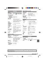
Page 47: ...bit 48 kHz 2 channel 16 bit Cassette Mini DV cassette Tape speed SP 18 8 mm s LP 12 5 mm s Maximum recording time SP 80 min using 80 min LP 120 min cassette Digital Still Camera Function Storage media SD Memory Card MultiMediaCard Compression system JPEG compatible File size 2 modes 1024 x 768 pixels 640 x 480 pixels Picture quality 2 modes FINE STANDARD Approximate number of storable images 墌 pg ...

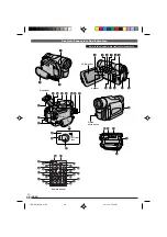
Page 48: ...E PLAY q 2 3 1 4 9 5 6 7 8 e r t y Q o u i W 0 w E p R j I s g f U P a O d k l A S D F G H h K J Y T Viewfinder Speaker LCD monitor Refer to this diagram while reading the instructions Remote Control Stereo microphone 1 GR D91US EN 41 56 02 11 20 5 34 PM 48 ...

Page 49: ...ector AV 墌 pg 16 33 Edit Connector EDIT 墌 pg 37 q S Video Input Output Connector S VIDEO 墌 pg 16 33 w Diopter Adjustment Control 墌 pg 8 e Recording Start Stop Button 墌 pg 12 r Shoulder Strap Eyelets 墌 pg 9 t POWER CHARGE Lamp 墌 pg 7 12 13 y Lock Button 墌 pg 13 u Power Switch PLAY OFF CHARGE 墌 pg 13 i Monitor Open Button 墌 pg 12 o Stud Hole 墌 pg 9 p Tripod Mounting Socket 墌 pg 9 Q MEMORY CARD Cover...

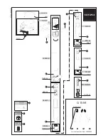
Page 50: ...HOTO BR I GHT r e t y o i u q w 6w 12 1 3 0 5 0 0 0 1 2 b i SOUND BLANK SEARCH VOLUME t DE 116 21 25 C M A 64 L p E W Q Y R T u BR I GHT 1 1 0 0 0 0 1 U I O u During Tape Recording Only During Tape Playback During Memory Card Recording Only During Memory Card Playback During Both Tape And Memory Card Recording 1 GR D91US EN 41 56 02 11 20 6 20 PM 50 ...

Page 51: ...d the shutter speed is being automatically adjusted 墌 pg 29 Appears when the white balance is adjusted 墌 pg 27 ⴣ Appears when the exposure is adjusted 墌 pg 26 Appears when backlight compensation is used 墌 pg 26 q Displays the selected Program AE with special effects 墌 pg 23 w Appears when the iris is locked 墌 pg 27 e Approximate zoom ratio Appears during zooming 墌 pg 13 r Appears during zooming Zo...

Page 52: ... DUB ERROR CANNOT DUB ON A LP RECORDED TAPE CANNOT DUB ON A 16BIT RECORDING CHECK TAPE S ERASE PROTECTION TAB Appears if Audio Dubbing is attempted on a tape recorded in the LP mode Appears if Audio Dubbing is attempted on a tape recorded in 16 bit audio Appears if A DUB e S on the remote control is pressed when the erase protection tab is set to SAVE 墌 pg 39 INSERT ERROR Appears if Insert Editing...

Page 53: ...SAFEGUARD MODE REMOVE AND REATTACH BATTERY The error indications E01 E02 or E06 show what type of malfunction has occured When an error indication appears the camcorder turns off automatically Remove the power supply battery etc and wait a few minutes for the indication to clear When it does you can resume using the camcorder If the indication remains consult your nearest JVC dealer E03 or E04 UNI...

Page 54: ... 25 MultiMediaCard 墌 pg 11 44 N Night Alive 墌 pg 23 A AC Adapter 墌 pg 7 8 Analog Input 墌 pg 31 33 Audio Dubbing 墌 pg 39 Auto Date 墌 pg 30 Auto Focus 墌 pg 25 Auto Playback 墌 pg 19 Auto Shut off 墌 pg 12 15 17 B Backlight Compensation 墌 pg 26 Battery Low 墌 pg 52 Battery Pack 墌 pg 7 8 44 Beep 墌 pg 30 Blank Search 墌 pg 15 Brighten The LCD Monitor 墌 pg 12 C Channels Left Right 墌 pg 32 Charge The Battery...

Page 55: ...g 13 Sepia 墌 pg 23 Set Remote Control VCR Code 墌 pg 36 Shuttle Search 墌 pg 14 Shutter Speed 墌 pg 23 Slow Motion Playback 墌 pg 14 35 Snapshot 墌 pg 17 25 Snapshot Mode 墌 pg 25 Snow 墌 pg 23 Sound Mode 墌 pg 28 31 32 Speaker Volume 墌 pg 14 Specifications 墌 pg 47 Sports 墌 pg 23 Spotlight 墌 pg 23 Squeeze 墌 pg 29 Still Playback 墌 pg 14 Strobe 墌 pg 23 T Tally 墌 pg 30 Tele Macro 墌 pg 29 Time Code 墌 pg 14 30...

Page 56: ...COPYRIGHT 2002 VICTOR COMPANY OF JAPAN LTD VICTOR COMPANY OF JAPAN LIMITED US Printed in Malaysia 1102 HO UN PJ 1 GR D91US EN 41 56_Malaysia 02 11 20 6 38 PM 56 ...

Reviews: