background image

Important Safety Precautions

Prior to shipment from the factory, JVC products are strictly inspected to conform with the recognized product safety and electrical codes of the
countries in which they are to be sold. However, in order to maintain such compliance, it is equally important to implement the following precautions
when a set is being serviced.

Fig.1

1. Locations requiring special caution are denoted by labels and in-

scriptions on the cabinet, chassis and certain parts of the product.
When performing service, be sure to read and comply with these
and other cautionary notices appearing in the operation and serv-
ice manuals.

2. Parts identified by the 

!

 symbol and shaded (        ) parts are

critical for safety.
Replace only with specified part numbers.

Note: Parts in this category also include those specified to com-

ply with X-ray emission standards for products using
cathode ray tubes and those specified for compliance
with various regulations regarding spurious radiation
emission.

3. Fuse replacement caution notice.

Caution for continued protection against fire hazard.
Replace only with same type and rated fuse(s) as specified.

4. Use specified internal wiring. Note especially:

1) Wires covered with PVC tubing
2) Double insulated wires
3) High voltage leads

5. Use specified insulating materials for hazardous live parts. Note

especially:
1) Insulation Tape

3) Spacers

5) Barrier

2) PVC tubing

4) Insulation sheets for transistors

6. When replacing AC primary side components (transformers, power

cords, noise blocking capacitors, etc.) wrap ends of wires securely
about the terminals before soldering.

Power cord

Fig.2

10. Also check areas surrounding repaired locations.

11. Products using cathode ray tubes (CRTs)

In regard to such products, the cathode ray tubes themselves, the
high voltage circuits, and related circuits are specified for compli-
ance with recognized codes pertaining to X-ray emission.
Consequently, when servicing these products, replace the cath-
ode ray tubes and other parts with only the specified parts. Under
no circumstances attempt to modify these circuits.
Unauthorized modification can increase the high voltage value and
cause X-ray emission from the cathode ray tube.

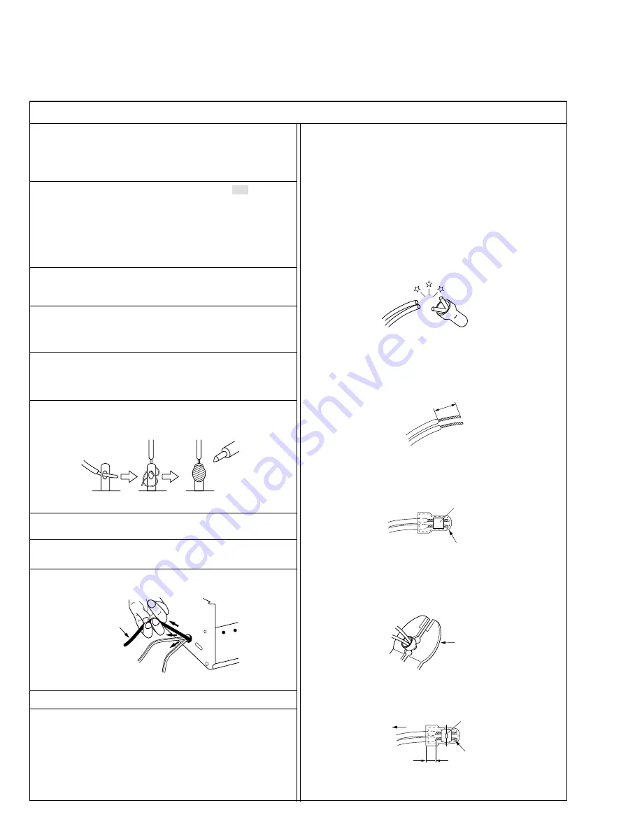
12. Crimp type wire connector

In such cases as when replacing the power transformer in sets
where the connections between the power cord and power trans-
former primary lead wires are performed using crimp type connec-
tors, if replacing the connectors is unavoidable, in order to prevent
safety hazards, perform carefully and precisely according to the
following steps.

1) Connector part number : 

E03830-001

2) Required tool : 

Connector crimping tool of the proper type which

will not damage insulated parts.

3) Replacement procedure

(1) Remove the old connector by cutting the wires at a point

close to the connector.
Important : Do not reuse a connector (discard it).

Fig.7

cut close to connector

Fig.3

(2) Strip about 15 mm of the insulation from the ends of the

wires. If the wires are stranded, twist the strands to avoid
frayed conductors.

15 mm

Fig.4

(3) Align the lengths of the wires to be connected. Insert the

wires fully into the connector.

Connector

Metal sleeve

Fig.5

(4) As shown in Fig.6, use the crimping tool to crimp the metal

sleeve at the center position. Be sure to crimp fully to the
complete closure of the tool.

I


Precautions during Servicing

7. Observe that wires do not contact heat producing parts (heatsinks,

oxide metal film resistors, fusible resistors, etc.)

8. Check that replaced wires do not contact sharp edged or pointed

parts.

9. When a power cord has been replaced, check that 10-15 kg of

force in any direction will not loosen it.

1.2

5

2.0

5.5

Crimping tool

Fig.6

(5) Check the four points noted in Fig.7.

Not easily pulled free

Crimped at approx. center

of metal sleeve

Conductors extended

Wire insulation recessed

more than 4 mm

S40888-01

Summary of Contents for GR-AX770U

Page 1: ...tem Luminance FM recording Color Converted sub carrier direct recording Conforms to VHS standard Cassette cassette Tape speed SP 33 35 mm sec 1 5 16 ips EP 11 12 mm sec 7 16 ips Recording time max SP 40 minutes EP 120 minutes with TC 40 cassette Operating temperature 0 C to 40 C 32 F to 104 F Operating humidity 35 to 80 Storage temperature 20 C to 50 C 4 F to 122 F Weight Approx 850 g 1 9 lbs Dime...

Page 2: ...EMBLY 1 1 SERVICE CAUTIONS 1 1 1 1 1 Precautions 1 1 1 1 2 How to read the disassembly and assembly 1 1 1 1 3 Connection of the wires 1 1 1 2 TOOLS REQUIRED FOR ADJUSTMENTS 1 2 1 3 DISASSEMBLY ASSEMBLY OF CABINET PARTS 1 3 1 3 1 Disassembly flow chart 1 3 1 3 2 Disassembly method 1 4 1 4 DISASSEMBLY ASSEMBLY OF CAMERA SECTION AND DECK SECTION 1 8 1 4 1 Flowchart of disassembly 1 8 1 4 2 Disassembl...

Page 3: ...e specified for compli ance with recognized codes pertaining to X ray emission Consequently when servicing these products replace the cath ode ray tubes and other parts with only the specified parts Under no circumstances attempt to modify these circuits Unauthorized modification can increase the high voltage value and cause X ray emission from the cathode ray tube 12 Crimp type wire connector In ...

Page 4: ... between terminals and surrounding metallic parts See table 1 below 4 Leakage current test Confirm specified or lower leakage current between earth ground power cord plug prongs and externally exposed accessible parts RF terminals antenna terminals video and audio input and output terminals microphone jacks earphone jacks etc Measuring Method Power ON Insert load Z between earth ground power cord ...

Page 5: ... kgf cm 1 1 2 How to read the disassembly and assembly For Cabinet Parts 1 Order of steps in Procedure When reassembling preform the step s in the reverse order These numbers are also used as the identifica tion location No of parts Figures 2 Part to be removed or installed 3 Fig No showing Procedure or Part Location C Cabinet CA Camera D Deck 4 Identification of part to be removed unhooked un loc...

Page 6: ...lder YTU94087 7 8 9 10 11 12 13 14 Camera stand YTU93079 Conn ring YTU92001 111 Gray Scale Chart YTU94133A Color Bar Chart YTU94133C Light box Assembly YTU93096A Extension connector YTU94145B 30 Service support system YTU94057 56 Cleaning cloth KSMM 01 16 15 17 PC cable QAM0099 002 Jig connector cable YTU93106A Communication cable YTU93107A 1 2 TOOLS REQUIRED FOR ADJUSTMENTS Table 1 2 1 ...

Page 7: ... used to JIG connector cable 13 JIG connector cable Connected to CN25 of the main board and used for measuring error rates etc 14 Communication Cable Connect the Communication cable between the PC ca ble and Jig connector cable when performing a PC ad justment 15 Service support system To be used for adjustment with a personal computer 16 PC cable To be used to connect the VideoMovie and a persona...

Page 8: ...breviations 2 S1 2 screws S1 4 L1a 4 Locking Tabs CN Connector Reference Notes NOTE 1 Destination of connectors Note Two kinds of double arrows in connection tables respectively show kinds of connector wires Flat wire Wire Con nector Connector CN3a 3 E VF B W MAIN CN12 20 C VF CN7701 C VF BL CN7801 MAIN CN11 CN5a 12 TOP OPERATION UNIT MAIN CN18 CN6a 13 REAR UNIT MAIN CN28 CN7a 2 MIC MAIN CN8 No of...

Page 9: ...1 5 Fig C4 Fig C3 Fig C5 3 COVER JACK S 3 4 S 3 5 S 3 6 S 3 7 S 3 8 S 3 9 S 3 10 S 3 11 S 3 12 L a 3 L b 3 CN a 3 4 S 4 13 S 4 14 S 4 15 5 17 S5 16 S5 L5c L5a L5b CN5a ...

Page 10: ...1 6 Fig C7 Fig C6 20 S6 L6a CN6a L6b 18 S6 6 19 S6 L7a 7 L7b 8 21 S7a 22 S7a 24 S7a CN7a 23 S7b 9 9 L7c L7c For DC LIGHT MODEL ONLY ...

Page 11: ...1 7 Fig C9 Fig C8 10 25 S8a 26 S8a 27 S8b 0 098N m 1 0kgf cm 0 098N m 1 0kgf cm 29 S9 28 S9 11 ...

Page 12: ...L2a CN2a CN2b CN2c CN2d CN2e CN2f CN2g CN2h CN2j 3 OP BLOCK D3 2 S3 CUSHON OP ASSEMBLY Incl CCD BOARD ASSEMBLY 4 FRAME ASSEMBLY D4 2 S4a 2 S4b S4c 5 CASSETTE HOUSING D5 4 S5 ASSEMBLY STEP LOC No PART Fig No REMOVAL UNLOCK RELEASE UNPLUG UNCLAMP UNSOLDER List of Abbreviations 2 S1 2 screws S1 4 L1a 4 Locking Tabs L1a CN Connector Reference Notes NOTE 1 Destination of connectors Note Two kinds of do...

Page 13: ...5 S 2 6 CN a 2 CN b 2 CN c 2 CN e 2 CN d 2 CN f 2 CN g 2 CN h 2 CN j 2 L a 2 2 CUSHION OP S 3 8 S 3 7 3 S c 13 4 0 108 N m 1 1 kgf cm S b 11 4 S b 12 4 S a 10 SHIELD CASE MAIN 4 S a 9 4 4 5 S 17 5 S 16 5 S 15 5 S 14 5 0 216 N m 2 2 kgf cm ...

Page 14: ...ntation of each item refering to the following table see Fig 1 5 1 Part Name Orientation CCD image sensor Mark is on the right viewed as indi cated by the arrow a Spacer rubber IC side is horizontal Optical LPF Marks are on the left and bottom viewed as indicated by the arrow a 2 Fix the CCD base assembly to OP block with the two screws S1a At that time be careful of the orienta tion 3 After compl...

Page 15: ...per wire to each pole of the loading mo tor as shown by the magnified view Fig 1 6 1 4 While holding down the cassette housing by hand con nect the jumper wires to a battery to run the mechanism to the EJECT position four unloading If this unloading operation is performed as the cassette housing is not held down by hand the front lid of the cassette may damage the tape when it is ejected 5 For tak...

Page 16: ...S S B C Y U A S R M T E E E R M A M M E E N A A A N U U U U U T T T O O O R I T T D D T E N E I A E R O C T L T T M E E L E O T C T E U S A I T M T M R Y M M I A L I O N S E E M C A M D T R E R N E E E A O G M M M E E N O O O F O N U F F F R F U F F F E F NCH 1 2 Display 1 Display 2 Fig 1 8 1 See to next page Set the POWER switch to turn on the M Press the MENU WHEEL once The first page of the DIS...

Page 17: ...0 DIGITAL EFFECT MOSAIC Display 4 Display 3 Refer to Fig 1 8 2 While the DEMONSTRATION mode is activated a word of DEMONSTRATION is appearing on the screen scrolling from right to left DENO MODE OFF ON EXIT R I T T D J D V T E N E I A L E I R O C T L T T I M D E E L E P O E T C T E O U S A I T M T I M R Y M M I A L I D O O N S E E M C A M D U T R E R N E N E T E A O G O M M M E E N O O O F 0 O S N...

Page 18: ...eference drawing Screw tightening torque Symbol No Removing order of screw Place to stick screw Reference drawing Screw tightening torque 25 26 27 28 29 Fig C9 Fig C8 1 2 3 4 5 6 7 8 9 10 11 12 13 14 15 16 17 1 2 3 4 5 Fig D5 Fig D2 Fig D1 Fig D3 Fig D4 I I I 1 2 3 Fig 1 5 1 DECK ASSEMBLY OP B LOCK ASSEMBLY MAIN ASSEMBLY I 0 196N m 2 0kgf cm II 0 098N m 1 0kgf cm III 0 118N m 1 2kgf cm IV 0 108N m...

Page 19: ... P Spring W Washer S Screw Unhook unlock release unplug or unsolder 6 Adjustment information for installation Refer to Exploded Views for Lubrication informa tion Roller Driver PTU94002 2 Jig connector cable YTU93106A Cassette torque meter PUJ50431 2 Alignment tape MHP C Alignment tape MHP LC Extension connector YTU94145B 30 1 2 3 4 5 6 1 ROLLER BASE ASSEMBLY T M1 S1 2 TENSION ARM ASSEMBLY T M1 P1...

Page 20: ... GEAR T M3 W3a BRAKE SUB GEAR T M3 W3a P R ARM ASSEMBLY T M3 W3b TU GUIDE ARM ASSEMBLY T M3 W3a LINK ARM ASSEMBLY T M4 W4 LED GUIDE T M4 S4a A C HEAD UNIT T M4 2 S4b q SLANT POLE BASE ASSEMBLY T M5 S5a w CAP MOTOR ASSEMBLY T M5 3 S5a e MOTOR BASE T M5 2 S5b S5c r BRUSH B M6 S6a t DRUM FINAL T B M6 2 S6b 2 S6c CATCHER y GUIDE RAIL T M6 8 S6d u POLE BASE SUP T M6 i POLE BASE TU T M6 o COVER PLATE T ...

Page 21: ... 30 35 7 34 3 9 5 2 36 4 27 28 29 1 18 15 14 16 17 22 19 21 20 37 31 26 23 13 25 24 11 10 Note When reinstalling the cassette housing to the set pay careful attention to the switch not to damage it Fig 2 2 1 TOP VIEW Fig 2 2 2 BOTTOM VIEW ...

Page 22: ...2 4 Fig M1 Fig M3 Fig M2 Fig M4 W1a W1a W1b S1 W1a P1 3 4 1 2 W2 S2 W2 W2 5 6 7 8 9 16 12 17 14 11 W3a 15 W3a W3a W3b S3a S3b P3 S3a S3a S3a S3a 10 13 W4 S4a S4b S4b 18 19 20 ...

Page 23: ...2 5 Fig M5 Fig M7 Fig M6 Fig M8 S5a S5a S5b S5a S5c 21 22 23 Catcher S6c S6c S6a S6d S6d S6d S6d S6b 24 25 26 27 28 S7 31 29 30 S8 S8 W8a W8b W8b 32 33 34 35 36 37 ...

Page 24: ... hole of the Loading gear T assembly to that of the deck Align one of the three holes of wheel gear to the deck hole Align the two holes of the Loading ring assembly to those of the deck Align the hole of the link lever assembly to the deck hole Align each one link lever assembly hole and deck hole to the hole at the control cam position Align this part to each Triangle mark Align this part to eac...

Page 25: ...on 5 Set the tracking control to the center position by simul taneously pressing the tracking and buttons and maximize the FM waveform by the tracking button 6 If the observed FM waveform is not flat adjust the height of the supply of take up guide roller with the roller driver Note To prevent the tape from damage turn the guide rollers slowly 7 By operating the tracking button both in and direc t...

Page 26: ...ler Pinch roller TU guide pole Tension pole 2 4 3 A C head height azimuth 1 Connect the jig connector cable to CN25 on the MAIN board 2 Connect the channel 1 scope probe to the audio output and connect the channel 2 scope probe to PB CTL 3 Playback the alignment tape 4 Set the tracking to its center range by pressing the and tracking controls simultaneously 5 Adjust screws A B and C approximately ...

Page 27: ... of the upper drum particularly video heads use fine woven cotton cloth or Kimwipe with al cohol soaks through Do not move the cloth but turn the upper drum counterclockwise Note Make sure not to move the cloth in the vertical di rection to the video head since it may cause dam age of the video heads 2 For cleaning of parts of the tape transport system ex cept the upper drum use fine woven cotton ...

Page 28: ...uble for connecting the jig connector cable NOTE 1 2 3 4 5 6 7 8 9 10 11 12 13 14 15 16 17 18 19 20 21 22 23 24 25 26 27 28 29 30 DIAL_MN CVF_B BWVFADJ CVF_G VF_RPD CVF_R GND PLI_AD GND NC GND VPP_7 8V JIGCN_SW DISCHG_L GND MCU_RST TCCS_TXD V_FF RXD V_TP_FM V_OUT V_OVL AO_SIG_J PB_CTL AL_3 2V TXD EJECT_SW NC NC NC DIAL_MN CVF_B BWVFADJ CVF_G VF_RPD CVF_R GND PLI_AD GND NC GND VPP_7 8V JIGCN_SW DIS...

Page 29: ...assis 2 Required test equipment 1 Color TV monitor 2 AC power adapter 3 Oscilloscope dual trace type observable 100 MHz or higher frequency It is recommended to use one observable 300 MHz or higher frequency 4 Digital voltmeter 5 Frequency counter with threshold level adjuster 6 Personal computer Fig 3 1 1 Connection for Service support system Note This adjustmentalls into a special adjustment tha...

Page 30: ... stopper completely 3 2 2 Centering Subject Alignment tape Stairstep Mode PB Equipment E VF Measurement point E VF screen Adjusting part Centering magnet CRT assy Specification The center of the E VF screen 1 While observing the viewfinder screen adjust the centering magnet to locate the stairstep in the center of the view finder screen 3 2 3 Vertical scanning Subject Camera picture Mode EE Equipm...

Reviews: