JVC GM-H40L2 Instructions Manual Download Page 17

17

Setting the Security Lock

When the Security Lock is set to “ON,” you need to enter the password when turning on the monitor. 
Without entering the correct password, you cannot perform any operations except for entering the password and 
turning off the monitor.

7

 To change the password

When shipped from the factory, the password is set to 
“0000.”  Change it to the 4 characters of your choice.

Available characters:

 0 – 9, A – Z, a – z

Remote control ONLY

1


Select “PASS ID SETTING” on the 
SECURITY LOCK sub menu of the set-up 
menu.

2


Press 

3

.

The password entering screen appears.

3


Enter the current password.

See “How to enter a password” below.
The password setting screen appears.

4


Enter a new password.

See “How to enter a password” below.

5


Press OK.

The cursor moves to the second line.

Enter the new password again for 
confirmation, then press OK.

•  If the password is different from the one entered 

in step 

4

, “PASS ID NG!” appears and the SECURITY 

LOCK sub menu is displayed. In this case, repeat 
from step 

1

.

7

 To activate the Security Lock

1


Select “SECURITY LOCK (: OFF)” on the 
SECURITY LOCK sub menu of the set-
up menu.

2


Press 

3

.

The password entering screen appears.

3

  Enter the password.

See “How to enter a password” below.
The Security Lock is set to “ON.”
•  After activating the Security Lock function, the 

password is required to turn on the monitor. Enter 
the password (see “How to enter a password” 
below).

*

*

  If the power-on timer (see “POWER-ON SET” on page 15) is 

activated, the monitor turns on at the specified power-on 
time without the password.

7

 To deactivate the Security Lock

1


Select “SECURITY LOCK (: ON)” on the 
SECURITY LOCK sub menu of the set-
up menu.

2


Press 

3

.

The password entering screen appears.

3

  Enter the password.

See “How to enter a password” below.
The Security Lock is set to “OFF.”

E N T E R   PA S S   I D   :  

R E E N T E R   PA S S   I D   :

PA S S   I D   S E T T I N G

0

S E C U R I T Y   L O C K

P L E A S E   E N T E R

PA S S   I D   :  

0

S E C U R I T Y   L O C K

P L E A S E   E N T E R

PA S S   I D   :  

0

How to enter a password

To enter a password, follow the procedure below.

Remote control ONLY

1


Press 

5∞

 to select a character.

•  The digit currently selected flashes, and “*” is 

displayed for other digits.

2


Press 

2


3

 to edit the next digit.

3


Press OK after entering all digits.

•  If the password is wrong, “PASS ID NG!” appears. 

Enter the correct password.

About the external control

This monitor has two external control terminals as follows:

• RS-232C terminal:

  Controls the monitor by external control equipment (a personal computer or a dedicated 

controller) (see “Using the serial communication” on page 18).

• RS-485 terminals:

  The following external control systems are available.

(1) 

Serial communication:

 Controls the monitor by external control equipment (a personal computer or a 

dedicated controller) (see page 18).

(2) 

IR OUT system:

 Controls other equipment by using the remote control supplied with this monitor.

(3) 

MAKE (make contact system):


Controls the function by short-circuiting the corresponding pin terminal to 

the GND pin terminal, or disconnecting (opening) it (see page 19).

(4) 

TRIG. (trigger system):

 Controls the function by inputting the pulse signal instantaneously to the 

corresponding pin terminal (see page 19).

Set the following items in “REMOTE SYSTEM” according to the external control terminal and control system you use 
(see page 14).

Control system

“REMOTE IN SEL.”  setting

“CNT. RJ45 OUT” setting

“CNT. RJ45 IN” setting

Serial 
communication 

RS-485

RJ-45

*

1

RS485

RS485

RS-232C

D-sub9

*

1

RS485

RS485

IR OUT system

Any

IR OUT

Any

MAKE system

RJ-45

RS485

MAKE

TRIG. system

RJ-45

RS485

TRIG.

*1

 For the monitor connected to the external control equipment, set “REMOTE IN SEL.”  according to the actual connection. Set other 

monitors to “RJ-45.”

NOTE

•  Control priority is as follows: MAKE or TRIG. (trigger) system > RS-485 system > Buttons on the remote control or the main unit
•  While the Control Lock is in use, you can use external control.

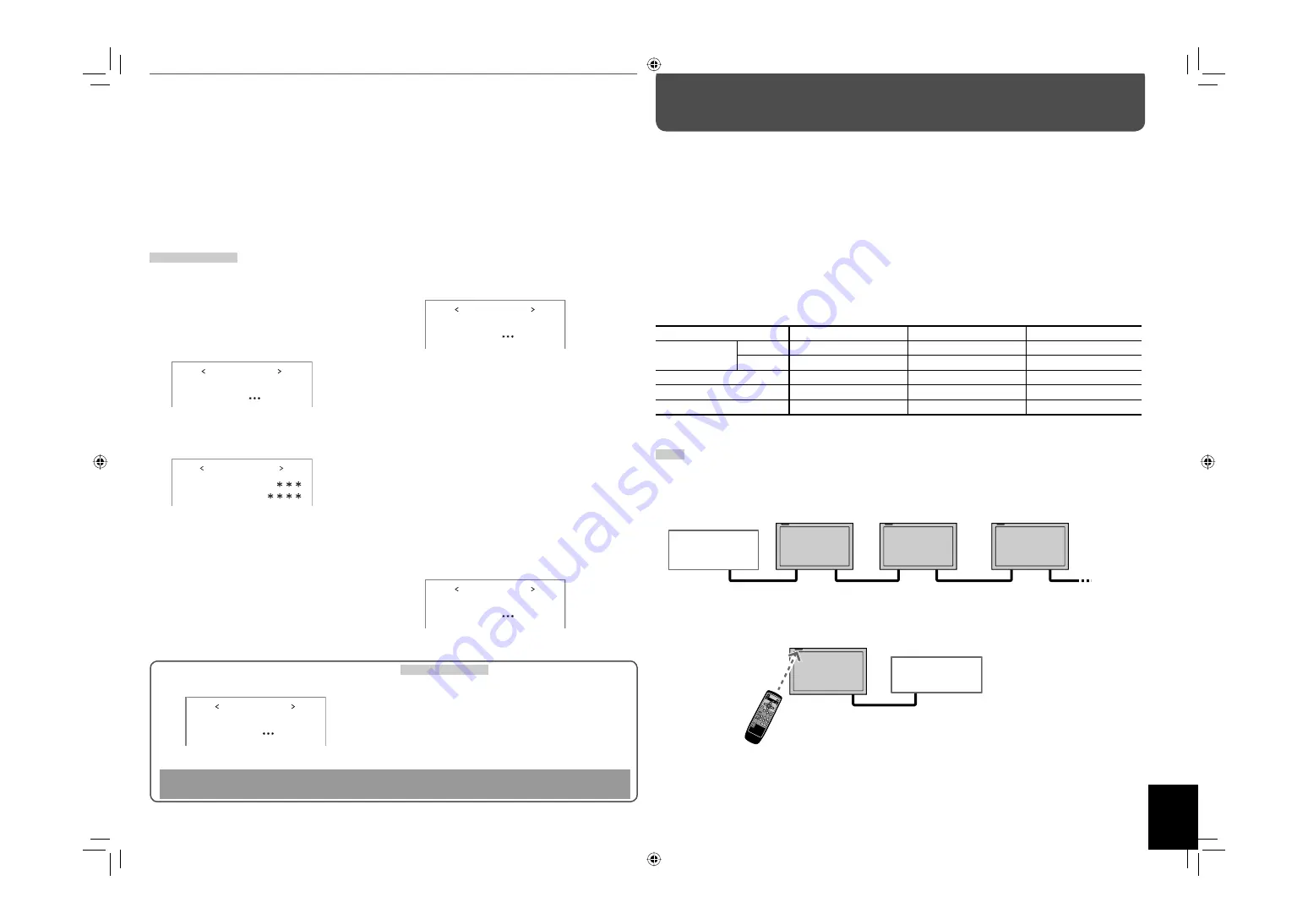
<Serial communication>

Several monitors can be controlled by connecting their RS-485 IN and OUT terminals. See also page 18.

<IR OUT system>

Control signals from the remote control are sent to external equipment via the RS-485 OUT terminal.

How to Use External Control

RS-485 IN or 
RS-232C

RS-485 
OUT

RS-485 
IN

RS-485 
OUT

RS-485 
IN

RS-485 
OUT

External control 
equipment

Karaoke 
component, etc.

Remote control (supplied)

RS-485 OUT

<MAKE/TRIG. system>

You can control the monitor by external control equipment

*2

. See also page 19.

*2

 External control equipment is not commercially available. Consult your dealer if you need a dedicated controller.

S E C U R I T Y   L O C K

P L E A S E   E N T E R

PA S S   I D   :  

0

S E C U R I T Y   L O C K

P L E A S E   E N T E R

PA S S   I D   :  

0

DO NOT forget the password!

If you forget the password, consult your dealer.

•  When shipped from the factory, the password is set to “0000.” 

GM-H40L2UA_resize-2.indd   17

GM-H40L2UA_resize-2.indd   17

06.7.28   1:44:45 PM

06.7.28   1:44:45 PM

Summary of Contents for GM-H40L2

Page 1: ...INSTRUCTIONS GM H40L2 LCD DISPLAY MONITOR LCT2200 001A GM H40L2UA_resize 2 indd 1 GM H40L2UA_resize 2 indd 1 06 7 28 2 15 04 PM 06 7 28 2 15 04 PM ...

Page 2: ...upply of your home consult your product dealer or local power company Warning Do not use the same power cord for AC 120 V as for AC 220 240 V Doing so may cause malfunction electric shock or fire Note for United Kingdom power cord only The plug on United Kingdom power cord has a built in fuse When replacing the fuse be sure to use only a correctly rated approved type re fit the fuse cover Consult ...

Page 3: ...nd the product For example cloth paper matches aerosol cans or gas lighters that present special hazards when over heated Maintenance Unplug this product from the wall outlet before cleaning Screen To avoid irreparable change in appearance of the screen such as uneven color discoloration scratches be careful about the following Do not paste or stick anything with any glues or adhesive tapes Do not...

Page 4: ... polarities are correct Follow the warnings printed on the batteries Battery life is about six months to one year depending on how much you use the remote control The batteries we supply are only for setting up and testing your monitor please replace them as soon as you need to If the remote control does not work properly replace the batteries Parts Identification Remote control POWER OFF button T...

Page 5: ...inal for monaural sound AUDIO IN B terminal STEREO terminal stereo mini jack Connect to the audio output terminals of the equipment connected to the VIDEO IN B terminal VIDEO IN A B terminals Connect video output terminals of equipment such as a VCR see page 8 VIDEO IN A terminal IN terminal BNC Connect to the video output terminals of playback equipment such as a VCR OUT terminal BNC Connect to t...

Page 6: ...r example if a disturbed image or noise due to electromagnetic interference occurs or if the infrared remote control malfunctions change the installation place When installing the monitor on a stand Front view Side view 150 6 150 6 50 2 50 2 200 7 7 8 15 5 8 200 7 7 8 100 4 100 4 100 4 Unit mm inch When mounting the monitor on the wall Front view Side view Unit mm inch When installing the monitor ...

Page 7: ...o ANALOG RGB When component signals are input to the RGB COMPO terminal Set INPUT B to COMPONENT When using the DVI D terminal Set INPUT B to DVI Note for component signals The monitor is compatible only with Y on sync signals The monitor is not compatible with composite sync Cs and separated sync HD VD signals Note for computer signals When analog RGB signals are input part of the picture may not...

Page 8: ...al BNC To S video output terminal To audio output terminal To RGB output terminal To digital output terminal D sub 15 pin cable DVI D cable Stereo mini jack cable S video cable BNC cable Stereo audio cable R L To component video or RGB output terminal BNC D sub 15 pin BNC conversion cable or Red Blue Green Synchronized signal H Synchronized signal V Connect the VIDEO IN A OUT terminal to the video...

Page 9: ...uter without changing the number of pixels This item is available only when one of the following signals is input WXGA 1280 WXGA 1360 1280 720 SXGA60 1 SXGA 60 1 SXGA 60 1 UXGA60 1 1Analog RGB only NOTE For some signals the aspect ratio cannot be changed or some modes cannot be selected While using multiple monitors see page 13 the aspect ratio is fixed to FULL When using the buttons on the main u...

Page 10: ...for operations described on this page use the main menu see page 11 or 13 Main window Main window Sub window Sub window Daily Operations cont Menu Operations On the main menu and set up menu you can make various adjustments such as picture quality or initial settings of the monitor For the configuration of the main menu and a detailed description of each item see pages 11 to 13 For the configurati...

Page 11: ... LOW OTHER sub menu Displays the adjustment bar which enables you to adjust the items in PICTURE SETTING except for CTI LTI while viewing the actual picture CTI LTI Adjusts the clearness of the picture OFF 1 2 reset Restores the default setting for all the items in PICTURE SETTING NOTE You can adjust the items in PICTURE SETTING for each picture mode Select a picture mode you want to adjust first ...

Page 12: ...d on the left side of is displayed on the left side of the screen and the input level for the channels indicated on the right side of is displayed on the right side of the screen OFF 1 2 12 34 31 24 123 456 1 8 BAR TYPE Selects the color of the audio level meter display 3COLORS 3 colors to indicate variations in input levels W 100 white W 50 half transparent BAR BRIGHTNESS Selects the brightness o...

Page 13: ...n see Displaying the current status on page 9 OFF ON 1080 1035 Selects a High Definition signal type 1080 60i or 1035 60i for the component signal to view the picture correctly 1080 1035 SUB HOUR METER Displays the hours of current use unit hour You can reset only this item ECO SENSOR Sets the eco sensor which enables you to adjust the brightness of the screen automatically according to the bright...

Page 14: ...ting color temperature HIGH MID LOW or OTHER on the main menu see PICTURE SETTING on page 11 NO SYNC FUNCTION Item To do Setting value NO SYNC DISPLAY Selects the screen color or sleep mode when no signal is being input OFF SLEEP sleep mode RED GREEN BLUE GRAY DELAY TIME Sets the time to change the screen color or sleep mode set in NO SYNC DISPLAY above after signals stops being input 5s 1min 30mi...

Page 15: ... the resistance of Horizontal sync Composite sync signal and Vertical sync signal when the component RGB input card option is inserted Normally select HIGH 1 kΩ If you see pictures flickering or blurring on the screen because of a long connecting cord set this to LOW 75 Ω Setting value HIGH LOW SYNC SELECT When a video input card option is inserted set the sync signal to use Setting value INT sync...

Page 16: ...E when WVGA60 or WXGA60 signal is input through the RGB COMPO terminal This item does not affect other signals and is not displayed for other signals Setting value STD WIDE SXGA SXGA Select SXGA when SXGA60 signal is input through the RGB COMPO terminal and SXGA when SXGA 60 or SXGA 60 signal is input through the RGB COMPO terminal This item does not affect other signals and is not displayed for o...

Page 17: ...This monitor has two external control terminals as follows RS 232C terminal Controls the monitor by external control equipment a personal computer or a dedicated controller see Using the serial communication on page 18 RS 485 terminals The following external control systems are available 1 Serial communication Controls the monitor by external control equipment a personal computer or a dedicated co...

Page 18: ...r Displays the MAIN MENU Quits the menu operation No data 8 B U P Cr Moves the cursor upward 5 No data 9 B D O W N Cr Moves the cursor downward No data 10 B A D J R Cr Makes setting adjustment 3 No data 11 B A D J L Cr Makes setting adjustment 2 No data 12 B E N T E R Cr Enters the password for the Security Lock No data 13 B S E T U P Cr Displays the SET UP MENU No data 14 B P W 1 Cr Turns on the ...

Page 19: ...ng off Muting on PIP Turns on off the PIP mode see page 10 Invalid Valid PBP Turns on off the PBP mode see page 10 Invalid Valid No function NOTE You cannot assign the same function to different pin terminals The TRIG trigger system switches each function by short circuiting for approx 1 second This is a female terminal Operation 1 Short circuit the 6th pin terminal External control to the 8th pin...

Page 20: ...splayed follow the procedure described on page 21 11 21 Color is poor or unstable Select the correct color system 13 The picture is cut or shifted toward one side Input signals scanning frequency etc are not appropriate Adjust the size and position properly 7 11 Menu does not appear or disappears quickly When INPUT B of INPUT CONFIGURATION is set to COMPONENT with a personal computer connected to ...

Page 21: ...r installation or improper location of the monitor In this case consult your dealer immediately to solve this improper installation and to improve the circumstances around the monitor If TEMP OVER appears in red TEMP OVER will be shown for about two minutes the monitor will shut off automatically then the self diagnostic lamps light in red If this happens switch off the main power using the POWER ...

Page 22: ...ut D sub 9 pin terminal x 1 For RS 232C control RS 485 input RJ 45 pin terminal x 1 For RS485 MAKE and TRIGGER control RS 485 output RJ 45 pin terminal x 1 For RS485 and IR OUT control AUDIO OUT MONITOR OUT Pin jack terminal x 2 L R Output impedance 600 Ω EXT SPEAKER Speaker output terminal L R Impedance 6 Ω to 8 Ω For easy understanding pictures and illustrations are shown by being emphasized omi...

Page 23: ...GM H40L2 LCD DISPLAY MONITOR 2006 Victor Company of Japan Limited 0706MKH MW VP GM H40L2UA_resize 2 indd 24 GM H40L2UA_resize 2 indd 24 06 7 28 1 45 15 PM 06 7 28 1 45 15 PM ...

Reviews: