background image

- 9 - 


 Installation


Precautions 

•  When installing the monitor on the wall, consult your dealer. 
•  Route the power cord and connection cables along the floor corners to avoid walking on 

them. 

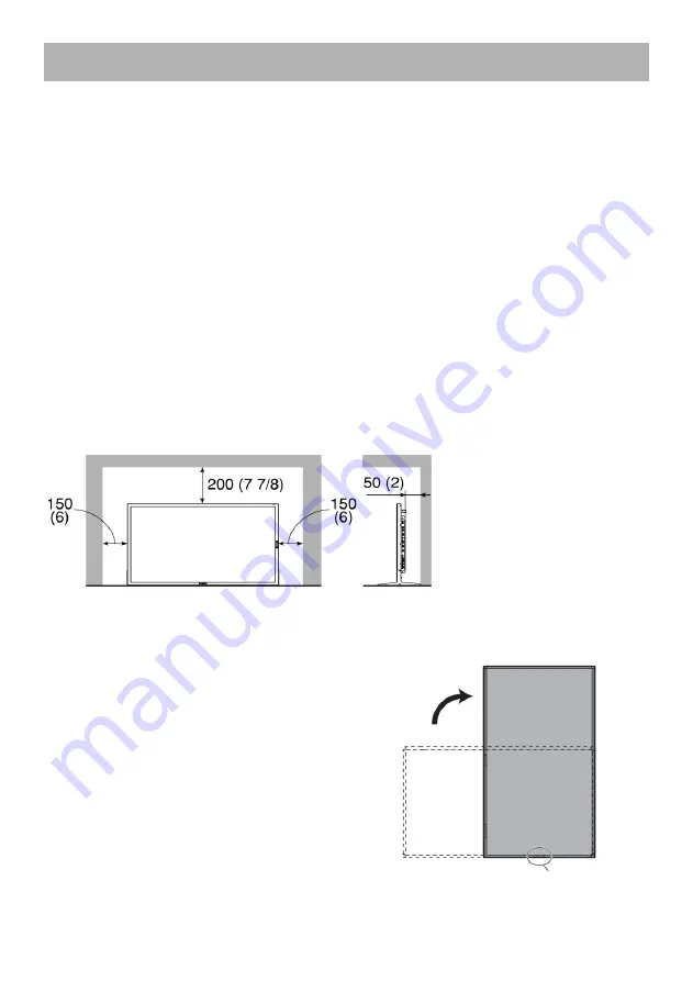
•  For good heat dissipation, try to leave the following distance of space (minimum) around 

the monitor (see diagram below). 

•  When installing the monitor near the ceiling or similar location, the remote control may not 

work correctly because of possible effects, such as reflections, from the surroundings. If 
this happens, move the monitor where it is free from these effects. 

•  The ambient temperature of the installation place should be within the range of 0°C to 40°C 

(32°F to 104°F)(slightly variable depending on the ambient conditions of the installation 
place). 

•  Do not install the monitor in such a way that the monitor and other AV equipment affect 

each other adversely. (For example, if a disturbed image or noise due to electromagnetic 
interference occurs, or if the infrared remote control malfunctions, change the installation 
place.) 


When installing the monitor on the supplied stand 


When installing the monitor vertically 

•  Make sure to install the monitor in the direction 

illustrated below. 

•  You can change the position of the JVC logo 

plate. Remove the sealing sticker on the place 
for the logo plate and fix the plate with the 
screws. 


Place for the logo plate


Unit: mm (inch) 

Front view 

Side view 

Summary of Contents for GM-552

Page 1: ......

Page 2: ...LCD DISPLAY MONITOR GM 552 GM 552D INSTRUCTIONS ...

Page 3: ...tructions should be read before the product is operated The safety and operating instructions should be retained for future reference All warnings on the product and in the operating instructions should be adhered to All operating instructions should be followed POWER CONNECTION The power supply voltage rating of this product is AC 100 V 240 V The power cord attached conforms to the following powe...

Page 4: ...efer all service to qualified service personnel Do not use the product for a long time if the sound is distorted Do not install this product in the following places in a damp or dusty room where the product is exposed to soot or steam such as near the cooking counter or a humidifier near heat sources where condensation easily occurs such as near the window Do not place this product on an unstable ...

Page 5: ...incorrect disposal of this waste in accordance with national legislation Business users If you wish to dispose of this product please visit our web page http www jvc eu to obtain information about the take back of the product Other Countries outside the European Union These symbols are only valid in the European Union If you wish to dispose of these items please do so in accordance with applicable...

Page 6: ...onnect the equipment into an outlet on a circuit different from that to which the receiver is connected Consult the dealer or an experienced radio TV technician for help IMPORTANT RECYCLING INFORMATION This product has a fluorescent lamp that contains mercury Disposal of these materials may be regulated in your community due to environmental considerations For disposal or recycling information ple...

Page 7: ... that the total of the ampere ratings on the products plugged into the extension cord do not exceed the extension cord ampere rating Also make sure that the total of all products plugged into the wall outlet does not exceed 10 amperes 12 Never push objects of any kind into this product through cabinet slots as they may touch dangerous voltageoints or short out parts that could result in a risk of ...

Page 8: ...kes all the openings If a vacuum cleaner is not available use a cloth and wipe it off Leaving the dust around the intakes may prevent proper temperature control and cause damage to the product Cabinet To avoid the deterioration or damages of the cabinet such as its paint s peeling away be careful about the following Do not wipe the cabinet using solvent such as alcohol thinner or benzine Do not ex...

Page 9: ...tents Safety Precautions 2 Installation 9 Connectors 11 Avilable Signals 12 Controls 14 Remote Control 15 Indicators 16 OSD Menu 16 How to use External Control RS 232C 24 Specifications 26 Trouble Shooting 30 ...

Page 10: ...llation place should be within the range of 0 C to 40 C 32 F to 104 F slightly variable depending on the ambient conditions of the installation place Do not install the monitor in such a way that the monitor and other AV equipment affect each other adversely For example if a disturbed image or noise due to electromagnetic interference occurs or if the infrared remote control malfunctions change th...

Page 11: ...Fix the power cord clamp as illustrated using the supplied screws at the pointed hole To prevent an accidental fall Fix the monitor to a wall by using strings Fixing the monitor Attach the hook not provided to the rear panel using M8 x 15 mm screws not provided Bind the hooks on the rear panel of the monitor to a wall or a pillar using durable string The holes on the base of the stand are also ava...

Page 12: ...out Command input HDMI HDMI typeA connector 1 in DVI D 24 pin DVI D connector 1 in RGB D sub 15 pin connector 2 one in one out AUDIO 1 Stereo mini jack 1 in S VIDEO Mini DIN 4 pin connector 1 in VIDEO BNC connector 2 one in one out loop thru out AUDIO 2 IN RCA pin L R x1 in AUDIO OUT RCA pin L R x1 out AC POWER Switch AC IN terminal ...

Page 13: ...0x480i 576 50i pixel repetition 720x576i 480 60p 720x480 576 50p 720x576 720 60p 1280x720 HD 720 50p 1280x720 HD 720 30p 1280x720 HD 720 25p 1280x720 HD 720 24p 1280x720 HD 1080 60i 1920x1080i HD 1080 50i 1920x1080i HD 1080 60p 1920x1080 3G 1080 50p 1920x1080 3G 1080 30p 1920x1080 HD 1080 25p 1920x1080 HD 1080 24p 1920x1080 HD 1080 30psF 1920x1080 HD 1080 24psF 1920x1080 HD 1080 25psF 1920x1080 HD...

Page 14: ...23 75 03 1024 768 85Hz 1024x768 68 667 85 00 1280 720 60Hz 1280x720 44 820 60 00 1280 768 60Hz 1280x768 47 760 59 99 1360 768 60Hz 1360x768 47 396 60 02 1152 864 75Hz 1152x864 67 500 75 00 1280 1024 60Hz 1280x1024 63 981 60 02 1400 1050 60Hz 1400x1050 64 744 59 95 1400 1050 60Hz 1400x1050 65 317 59 98 1600 1200 60Hz 1600x1200 75 000 60 00 Some signals may not be displayed normally even if its freq...

Page 15: ...ut displays INFORMATION FREEZE and freeze the picture Press any button release a freeze By a scene the motion picture may not still completely Press DOWN button once time on RGB input displays INFORMATION AUTO ADJUST and starts AUTO ADJUST Press the buttons to scroll the cursor to desired item in OSD menu 4 MENU OK Button Press the button to pop up the OSD main menu The enter key as for function s...

Page 16: ...T SELECT SDI SDI input signal displays MUTING AUDIO Mute on off VOLUME Volume up VOLUME Volume down UP Cursor moves UP VOLUME up Refer to P 14 No 3 LEFT Cursor moves Left MENU OK MENU OSD display OK RIGHT Cursor moves Right DOWN Cursor moves down VOLUME down AUTO ADJUST Refer to P 14 No 3 KEY LOCK Lock Unlock Control key and Remote control DISPLAY STATUS display on off INPUT mode and SIGNAL inform...

Page 17: ... Menu MAIN MENU Press or to select an item and then Press MENU to confirm the selection When finish the selection close by EXIT menu To fix must finish by EXIT menu VIDEO S VIDEO DVI HDMI SDI RGB MAIN ADJUST VIDEO S VIDEO HDMI VIDEO SDI RGB DVI HDMI DVI 1 Press Up Down buttons to select an icon 2 Press MENU button to enter 3 Press Up Down buttons to adjust value 4 Press MENU button to return 5 Ret...

Page 18: ...ENABLE DISABLE NR Select the Noise reduction level OFF LOW HIGH EXIT Press MENU button to return to the main menu To fix must finish by EXIT menu COLOR TEMP ADJ Set the color temperature of the LCD 1 Press Up Down buttons to select an icon 2 Press MENU button to enter 3 Press Up Down buttons to adjust value 4 Press MENU button to return 5 Return to MAIN MENU by EXIT COLOR TEMP Select the color tem...

Page 19: ... the main menu To fix must finish by EXIT menu IMAGE ADJUST RGB only 1 Press Up Down buttons to select an icon 2 Press MENU button to enter 3 Press Up Down buttons to adjust value 4 Press MENU button to return 5 Return to MAIN MENU by EXIT AUTO ADJUST Press MENU buttons to adjust automatically H Position V Position Phase Clock H POSITION Adjust the horizontal position Value 00 100 V POSITION Adjus...

Page 20: ...n to MAIN MENU by EXIT PIP PBP Select the style of sub picture OFF PI P PBP SOURCE Select the sub picture input source The combination of PIP and PBP is 1 Main screen is one of RGB DVI HDMI SDI and PIP or PBP screen is one of VIDEO S VIDEO 2 Main screen is one of VIDEO S VIDEO and PIP or PBP screen is one of RGB DVI HDMI SDI LOCATION Select the PIP LOCATION value 0 3 RATIO Select the PIP size valu...

Page 21: ...t to 4 4 and MULTI POSITION is set to 10 1 Press Up Down buttons to select an icon 2 Press MENU button to enter 3 Press Up Down buttons to adjust value 4 Press MENU button to return 5 Return to MAIN MENU by EXIT MULTI SIZE Select size OFF 2x1 2x2 3x3 4x4 5x5 MULTI POSITION Set the MULTI POSITION 01 25 SEAMLESS Look like seamless on Multi Display OFF ON EXIT Press MENU button to return to the main ...

Page 22: ...rn to MAIN MENU by EXIT VOLUME Adjust the VOLUME value 00 100 MUTING Select the audio muting function ON OFF HDMI AUDIO Select HDMI AUDIO DIGITAL AUDIO1 DIGITAL Output the digital audio signal on HDMI AUDIO1 Output the input signal of AUDIO1 Stereo mini jack 8CH SOURCE L R GM 552D only Select each the output in SDI embedded audio channel CH1 CH8 EXIT Press MENU button to return to the main menu To...

Page 23: ...tion ON OFF Adjust the brightness of the screen automatically according to the brightness of the room When select ECO SENSOR GREEN MODE become to OFF ID NUMBER Select ID NUMBER 01 99 This number is used by the specified adjustment with IR remote control Can control a only target monitor in many monitors Example for using the specified adjustment with IR remote control 1 Set ID number 05 in this me...

Page 24: ...se POWER SAVING mode by no signal press POWER button INPUT SELECT button or REMOCON s POWER ON button SDI When no signal is come in become Stand by mode after about 10 sec LED indicator is orange STATUS DISPLAY Displays status on LEFT UPPER when turn on or change input signal 4HOUR SHUTDOWN Set the monitor to turn into Stand by mode when no operation status continues for about 4 hours In case of c...

Page 25: ...mmunication Code ASCII Code Command outline When the monitor is turned on the external control is not ready To start communication send the connection command from the external control equipment To terminate the communication send the termination command from the external control equipment Example of communication procedures Commands starting with are operation commands from the external control e...

Page 26: ... 0 Cr Turns off the monitor No data 15 B I N A Cr Selects Input VIDEO No data 16 B I N B Cr Selects Input RGB No data 17 B I N C Cr Selects Input DVI No data 18 B I N D Cr Selects Input S VIDEO No data 19 B I N E Cr Selects Input HDMI No data 20 B I N F Cr Selects Input SDI No data 21 B D I S P Cr Displays the status No data 22 B V P L S Cr Turns the volume up No data 23 B V M N S Cr Turns the vol...

Page 27: ... 4 kg 69 1 lbs without the stand External dimensions with the stand without the stand Width 1272 6 mm 50 1 8 1266 6 mm 49 7 8 Height 745 5 mm 29 3 8 741 4 mm 29 1 4 Depth 360 0 mm 14 1 4 75 7 mm 3 Power requirements AC 100 V 240 V 50 Hz 60 Hz Rated input current 1 8 A Operating conditions Temperature Operating 0 C to 40 C Storage 20 C to 60 C Humidity non condensing Operating 20 to 85 Storage 10 t...

Page 28: ...T 656 SMPTE259M EMBEDDED AUDIO SMPTE299M SMPTE272M Analog AUDIO 500 mV rms RS232C How to use the serial communication on page 24 DC OUT DC 12 V output Max 350 mA For easy understanding pictures and illustrations are shown by being emphasized omitted or composed and may be slightly different from actual products Design and specifications are subject to change without notice All company names and pr...

Page 29: ... 28 Specifications cont Dimensions Screw size 8 M8 depth 15 mm VESA standard Unit mm inch ...

Page 30: ...lock shield 7 DDC Data IS GND 23 T M D S Clock 8 NC 16 Hot Plug Detect 24 T M D S Clock Specifications of the RGB IN terminal Pin No Signal name Pin No Signal name 1 Red 9 5 V 2 Green 10 GND 3 Blue 11 GND A 12 DDC Data 5 GND 13 HD 6 GND 14 VD 7 GND 15 DDC Clock 8 GND External GND Specifications of the Y C terminal Connect it to the S video output terminal Pin No Input signal 1 GND Y 2 GND C 3 Y 4 ...

Page 31: ...No sound Adjust the volume level Select MUTING OFF by AUDIO SETTING menu or Press MUTING button on REMOCON Connect the signal cable firmly Turn on the power of the connected component and set the output correctly 15 21 NO SYNC appears Select the correct input with INPUT SELECT buttons Connect the signal cable firmly Turn on the power of the connected output video signals Or check if the video outp...

Page 32: ... 31 Note ...

Page 33: ...GM 552 GM 552D LCD DISPLAY MONITOR ...

Reviews: