4
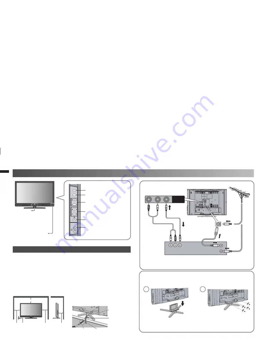
TV/VIDEO
MENU/OK
CHANNEL
VOLUME
150mm 50mm
150mm
200mm
50mm
6)$%/
6)$%/
2
,
6
Set up and connections
Care when setting
Hole for belt
(under the stand)
Belt (provided)
Screw (not provided)
Power lamp
ON :
Lit
(Blue)
OFF
:
Unlit
Power lamp lights
while the TV is on.
• “Power Lamp” (P. 11)
Remote control
sensor / Eco Sensor
Switch between TV / VIDEO
devices
Display on-screen menu / set
Change channel / Page /
Hyper Scan Function (P. 3)
Volume / Adjust
Power On / Off
To Headphone (P. 5)
■
Power requirements
•
Connect the power cord only to a 110-240V, 50/60Hz AC outlet.
■
When attaching the TV to the wall, use the optional JVC wall
mounting
unit
•
Consult a quali
fi
ed technician.
•
JVC assumes no responsibility for damage due to improper mounting.
•
LT-42Z49 : 400 mm x 200 mm mount which conforms to VESA standards.
■
Installation requirements
•
To avoid overheating, ensure the unit has ample room.
• After all the connections have been made, insert the plug into an
AC outlet.
Connect an aerial and VCR / DVD Player
AERIAL
OR
VCR (DVD Player)
- If you have any problem with assembly, please contact a retailer or
a dealership.
Note: 4 screws included.
Stand Assembly
- Insert the stand into the panel at the position where the screw
holes are, and fasten the screws.
•
To prevent the TV from falling, thread
the belt through the hole on the back of
the stand and secure it to the TV rack.
Screw for attach
the belt to the
stand (provided)
GGT0312-001A-H-EN.indd 4
GGT0312-001A-H-EN.indd 4
5/6/09 4:30:48 PM
5/6/09 4:30:48 PM


