background image

14

15

The top portion of the Camera Unit’s control panel 

is used to control intercom operation of the camera 

operator’s headset. These controls consist of: a push-

to-talk (PTT) switch, volume control buttons, and 

indicator LEDs. There are additional controls locat-

ed next to the headset connector for Mic Gain and 

Sidetone adjustment.  Mic Gain and Sidetone level are 

adjusted using a small screwdriver.


The intercom headset connector can be used with 

industry standard dual-muff or single-muff headsets.  

Intercom Belt Packs cannot be plugged into the Cam-

era Unit. When using dual-muff headsets, identical 

audio will be present in both ears.


The volume controls allow for a mix of both intercom 

channels and program audio all to be listened to in 

the headset simultaneously. The LED above each 

channel’s set of volume control buttons will illu-

minate whenever audio is present on that channel.  

When adjusting the volume, these LED’s will rapidly 

blink 3 times whenever the min or max volume set-

ting has been reached.


The intercom Talkback switch, or PTT switch, provides 

Momentary/Latching operation of the headset mi-

crophone to allow the operator to talk on a particular 

intercom channel, or on both channels simultaneously.


For Momentary Mode, press and hold the PTT switch 

up or down towards the intercom channel you wish 

to speak on and then speak into the microphone. 

The TALK and the selected intercom channel LED’s 

will blink and the mic will remain open while the PTT 

switch is held.  Release the PTT switch when finished 

talking.  The mic will close and the TALK and channel 

LED’s will turn off.


Latching Mode can be used for longer-term, hands-

free operation. To talk on channel 1, quickly toggle 

the PTT switch upwards towards CH1 and release.  

The mic will latch open and the TALK and CH1 LED’s 

will blink continuously.  When finished talking, quick-

ly toggle the PTT switch upwards again and release.  

The mic will then close and the TALK and CH1 LED’s 

will turn off.


To talk on channel 2, quickly toggle the PTT switch 

downwards towards CH2 and release. The mic will 

latch open and the TALK and CH2 LED’s will blink 

continuously. When finished talking, quickly toggle 

the PTT switch downwards again and release.  The mic 

will close and the TALK and CH2 LED’s will turn off.


To talk on both channels 1 and 2 simultaneously, first 

quickly toggle the PTT switch upwards towards CH1 

and release. The mic will latch open and the TALK 

and CH1 LED’s will blink continuously.  Next, quickly 

toggle the PTT switch downwards towards CH2 and 

release. The mic will stay open and now the TALK, 

CH1 and CH2 LED’s will all blink continuously.  When 

finished talking, quickly toggle the PTT switch up-

wards and release to disengage CH1 (the CH1 LED will 

turn off) then quickly toggle the PTT switch down-

wards and release to disengage CH2 (the CH2 LED 

will turn off).  The mic will close and the TALK, CH1 

and CH2 LED’s will all turn off.


An external switch connected to the DB-15 GPIO 

connector on the Camera Unit may also be used to 

control Intercom Talkback operation, please refer to 

the pinout guide for pinout information.  Two mic 

trigger GPI pins are provided, one for CH1 and one for 

CH2. A single SPDT momentary type switch or 2 SPST 

switches may be used.


Intercom Talkback operation can also be controlled 

using the REC button on the Camera’s Lens.  Note 

that this requires GY-HM890U camera firmware 

A518-00FB, or later, and this option can be enabled 

in the Camera’s menu under: Camera Function à Lens 

REC à (ICOM2, ICOM1, REC). Momentary and Latching 

operation is supported from the REC button only on 

the intercom channel that is selected in the menu.  

Both channels cannot be activated simultaneously 

from the REC button.

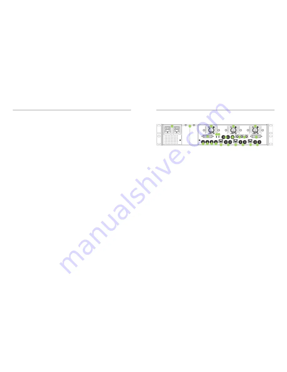
Intercom Operation

1. 

AC Mains Input 1 & 2 Connector:

 Provides power 

to the base unit electronics and the camera head 

units. AC Mains 1 is primary AC power input. AC 

Mains 2 only provides redundant power to the 

base station.

2. 

OpenGear Option Slot 1 & 2:

 For future use.

3. 

Camera 1, 2, & 3 Hybrid Fiber-Optic Connector: 

Use either SMPTE or Neutrik cable (depending  

on option ordered) to connect cameras to base 

unit. Carries all data between camera head unit 

and base unit and provides power to camera  

head as well.

4. 

Program Audio & Intercom DB25 Connector: 

Intercom and PGM Audio signals are connected 

here

5. 

Return 1, 2, & 3 SDI Video Input BNC Connector: 

Return video input channels to the base which 

are sent to the three camera units..

6. 

Timecode Input BNC Connector:

 Timecode input 

to Base Unit which is then sent to the three Cam-

era Head Units.

7. 

Intercom 2-Wire/4-Wire Selector Switch:

 Selects 

between 2-Wire mode or 4-Wire mode

8. 

Wire Intercom Autonull Switch: 

Toggling it up 

performs an automatic nulling function on inter-

com CH1. Toggling it down performs this function 

on intercom CH2.

9. 

Video Reference Input BNC Connector (looping): 

Video input reference signal is connected here. 

10. 

Camera 1 Timecode Output BNC Connector: 

Timecode signal sent from Camera 1 thru Camera 

Head 1 Unit.

11. 

Camera 1, 2, & 3 RCP Connector:

 Remote control 

panel inputs

12. 

Tally & GPIO DB25 Connector:

 Connect Tally and 

GPIO signals for each camera here.

13. 

Ethernet Connector: 

Cameras 1, 2, & 3 

10/100/1000 mbs Ethernet port connections.

14. 

Camera 1, 2, & 3 SDI Video Output A & B BNC 

Connector: 

SDI video channel from cameras  

1, 2, & 3 available at these connectors. Two  

copies of each camera’s video output are  

provided on these BNC’s. 

Detailed Description: Base Station – Connectors & Controls

2

1

3

3

3

4

6

7

9

8

10

11

11

12

14 

13 

14  

13  

14 

13 

5

5

5

Summary of Contents for FS-900

Page 1: ...JVC USER MANUAL FS 900Triple Studio Camera Interface System 110 Newton Place Hauppauge NY 11788 800 488 8378 516 671 7278 sales multidyne com www multidyne com FIBER FIRST ...

Page 2: ... base station RX with a single fiber optic cable which can be located near the camera or miles away Contents Important Safety Instructions 4 Laser Safety Information 5 Unpacking the FS 900 Triple Studio Camera Interface System 6 Installation Instructions 6 FS 900 System Description 8 Camera Interface Signal Paths 9 FS 900 JVC Triple Studio Camera Interface System Components 10 Detailed Description...

Page 3: ...quires proper procedures or practices to prevent injury or death to personnel Cautions indicate proper procedures or practices to prevent damage to equipment or property Warning The safe operation of this product requires that a protective earth connection be provid ed A grounding conductor in the equipment s mains supply cord provides this protective earth To reduce the risk of electrical shock t...

Page 4: ...ne cord 1 Mounting Hardware kit Figure 4 Camera and Silverback connections Figure 5 Final mount Neutrik Option Qty Description 1 FS 900BS1N Base Station 3 FS 900CAM1N Camera Head 3 Return video cables 3 Hirose Power cables 1 Line cord 1 Mounting Hardware kit Figure 3 Attaching PCB connector Figure 2 Attaching camera mount plate Step 4 Camera and Silverback connection Connect the MCX connector the ...

Page 5: ...ase Station 2 The FS 900 Camera Head Model numbers of available options FS 900BS1S Base Station with SMPTE connectors FS 900BS1N Base Station with Neutrik connectors FS 900CAM1S Camera Head with SMPTE connectors FS 900CAM1N Camera Head with Neutrik connectors FS 900 System Description 3Gb s HD SDI 1 camera video 3Gb s HD SDI PGM return 1 video 3Gb s HD SDI return 2 video Prompter SDI HDMI common 2...

Page 6: ...standard broadcast camera systems The rigorous qualification and intermateability testing program guarantees consistent and reliable results with all compliant systems Detailed Description Camera Head Unit Connectors FS 900 JVC Triple Studio Camera Interface System Components 1 Battery Connector Anton Bauer Gold mount or V mount 2 Fiber Optic Connector Use either SMPTE or Neutrik cable depending o...

Page 7: ... talkback 3 Intercom Channel 1 2 Talk Active LED Indicator Blinks when the PTT switch has been used to enable talkback on CH 1 or CH2 4 Intercom Channel 1 2 Audio Presence LED Indicator Illuminates when audio is present 5 Program Audio Presence LED Indicator Illuminates when audio is present on either of the two Program Audio channels sent from the Base to the Camera Head units 6 Intercom Channel ...

Page 8: ...quickly toggle the PTT switch up wards and release to disengage CH1 the CH1 LED will turn off then quickly toggle the PTT switch down wards and release to disengage CH2 the CH2 LED will turn off The mic will close and the TALK CH1 and CH2 LED s will all turn off An external switch connected to the DB 15 GPIO connector on the Camera Unit may also be used to control Intercom Talkback operation pleas...

Page 9: ...SDI video RCP data and Fiber Link from Camerasis present 3 SDI Return 1 2 3 Video Presence LED Indicator Illuminates when the Return video channels input has a valid signal on it 4 Intercom Ch1 Ch2 Audio Presence LED Indicator Illuminates when the Intercom Ch1 Audio channel has a valid audio signal on it 5 Program Audio Presence LED Indicator Illuminates when the Program Audio channel has a valid ...

Page 10: ...18 19 Signal Flow Camera Head Signal Flow Base Unit ...

Page 11: ...atus Fiber Status A V Status System Status Back Home Cam Top Menu Camera System Status Camera 1 Camera 2 Camera 3 Back Home Base Fiber Status Menu Base Fiber Status Cam1 Cam2 Cam3 Rx1 xxdBm xxdBm xxdBm Rx2 xxdBm xxdBm xxdBm Rx3 xxdBm xxdBm xxdBm Back Home Base A V Status Menu Base Video Status Cam1 SD HD 3G Ret1 SD HD 3G Cam2 SD HD 3G Ret2 SD HD 3G Cam3 SD HD 3G Ret3 SD HD 3G Ref NTSC PAL HD Back ...

Page 12: ...Home Camera 3 System Status Menu Cam3 System Status CPU Rev ver FPGA Rev ver Vin xx x V Power xx x W Back Home Operation Camera 1 Top Menu Camera 1 Menu Fiber Status A V Status System Status Back Home Camera 1 Fiber Status Menu Cam1 Fiber Status Rx Pwr Temp 1 xxdBm deg C 2 xxdBm deg C 3 xxdBm deg C 4 xxdBm deg C 5 xxdBm deg C Back Home Camera 1 A V Status Menu Cam1 Video Status Cam1 SD HD 3G Ret1 ...

Page 13: ... Type SMPTE EBU LTC Inputs Unbalanced 15Vp p max Outputs Unbalanced 3Vp p max Connector Camera Unit Internal Connector Base Unit BNC Technical Specifications Technical Specifications SDI Video Interface SMPTE ST259 ST292 ST424 Data Rate 270Mbps 1 5Gbps 3Gbps Input output Level 800mVp p Input output Impedance 75 Ohms Connector Camera Unit BNC Connector Base Unit BNC Embedded Audio Supported Yes Vid...

Page 14: ...put 2 4 Wire Intercom Ch1 Output 15 4 Wire Intercom Ch2 Output 3 GND 16 GND 4 4 Wire Intercom Ch1 Input 17 4 Wire Intercom Ch2 Input 5 4 Wire Intercom Ch1 Input 18 4 Wire Intercom Ch2 Input 6 PGM Audio Ch1 Input 19 PGM Audio Ch2 Input 7 PGM Audio Ch1 Input 20 PGM Audio Ch2 Input 8 GND 21 GND 9 GND 22 N C 10 Intercom MIC Kill GPI Input 23 N C 11 N C 24 N C 12 GND 25 GND 13 GND Base Unit GPIO Connec...

Page 15: ...elect GPI Input 13 N C 6 GND 14 N C 7 GND 15 12VDC Output 8 GND Camera Unit Audio Connector Pinout Number Description Number Description 1 GND 6 PGM Audio Ch1 Output 2 PGM Audio Ch1 Output 7 GND 3 PGM Audio Ch2 Output 8 PGM Audio Ch2 Output 4 GND 9 N C 5 N C Camera Unit Intercom Headset Audio Connector Pinout Number Description 1 GND 2 MIC Input 3 GND 4 Audio L Output 5 Audio R Output Camera Unit ...

Page 16: ...110 Newton Place Hauppauge NY 11788 800 488 8378 516 671 7278 sales multidyne com www multidyne com 2016 MultiDyne Inc MDDOC00170 RevA November 2016 ...

Reviews: