background image

22

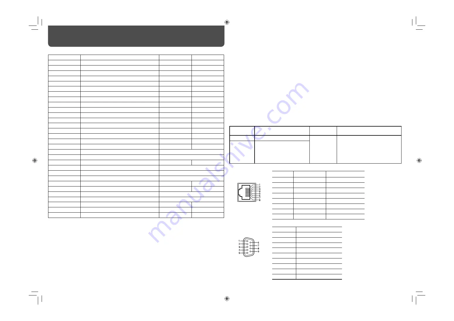
<Functions controlled by the MAKE/TRIGGER system>

Display

Functions to be controlled

Opening

Short-circuiting

TALLY SEL

Selects the color of the tally lamp.

Green

Red

SDI 1

Changes the input to “SDI 1.”

Invalid

Valid

SDI 2

Changes the input to “SDI 2.”

Invalid

Valid

DVI

Changes the input to “DVI.”

Invalid

Valid

COMP./RGB

Changes the input to “COMPO./RGB”

Invalid

Valid

VIDEO 1

Changes the input to “VIDEO 1.”

Invalid

Valid

VIDEO 2

Changes the input to “VIDEO 2.”

Invalid

Valid

EXT.SYNC

Changes the sync signal.

Internal sync

External sync

3G-B.DS

Selects the “3G SDI LEVEL B” data stream.

DS 1

DS 2

DUAL LINK

Turns on or off “SDI DUAL LINK.”

Off

On

A.MARKER

The area marker indication

Off

On

S.MARKER

The safety marker indication

Off

On

FRAME

Indication of the area of the specified aspect ratio

Off

On

C.MARKER

The center marker indication

Off

On

MARK.SEL

Selects the items of “MARKER”*

1

Non-“R-” items

“R-” items

ASPECT

Changes the aspect ratio.

4:3

16:9

1:1

Displays in 1:1 mode.

Off

On

STATUS

Status display*

2

 “On the Status Display” on page 7

L.METER

Audio level meter display

*

3

TIME CODE

Time code display

Off

On

SOURCE ID

 “SOURCE ID” in “INFORMATION” on page 19

*

4

WAVE FORM

Wave form monitor display

*

5

VECTOR

Vector scope display

*

5

C.C

Closed caption display

Off

On

COLOR OFF

Color off

Color

Monochrome

SCR CHECK

Screens check

*

6

I/P MODE

Change a mode according to a input picture.

*

7

MUTING

Muting on/off

Off

On

DIMMER

Change the intensity of the button lamps.

NORMAL

DARK

– – –

No function

*

1

 Selects which functions in “MARKER” are activated, non-“R-” items or “R-” items (

 “MARKER”  on page 13).

*

2

 Displays the information shown when INPUT SELECT button of the current input is pressed (

 “On the Status 

Display” on page 7). While controlling with the MAKE system, the information is displayed only at the moment of 
short-circuiting.

*

3

 While controlling with the MAKE system, the level meter is switched between displayed (short-circuiting) and 

hidden (opening). When “LEVEL METER ch” is set to “OFF,” the level meter is not displayed (“NO EFFECT” 
appears).

  While controlling with the TRIGGER system, the pattern of the audio channel display is switched.
*

4

 While controlling with the MAKE system, the available set-up options will be the setting value currently selected 

in “SOURCE ID” (“ON” or “AUTO” [short-circuiting]) and “OFF” (opening). While controlling with the TRIGGER 
system, uses the same set-up option as those in the SET-UP MENU (

 “SOURCE ID” in “INFORMATION” on 

page 19).

External Control 

(cont.)

*

5

 While controlling with the MAKE system, the wave form monitor and vector scope is switched between 

displayed (short-circuting) and hidden (opening) regardless of the “AUTO OFF” setting in the MAIN MANU. 
While controlling with the TRIGGER system, the screen is switched in the same way as when pressing the 
SCOPE button (


e

 on page 6). If the wave form monitor and vector scope are input at the same time, the 

wave form monitor is displayed.

*

6

 While controlling with the MAKE system, the screen is switched between normal screen (opening) and blue 

screen (short-circuiting). While controlling with the TRIGGER system, the screen changes in the same way as 
when pressing SCREENS CHECK button (


q

 on page 6).

*

7

 Must be controlled with the TRIGGER system. The mode changes in the order of “NORMAL” 

\

 “CINEMA” 

\


“FIELD.” (This function cannot be controlled with the MAKE system.)

•  You cannot assign the same function to different pin terminals.
•  The TRIGGER system switches each function by short-circuiting the pin terminal for about 1 second and 

opening it.

7

 Using the serial communication

You can control the monitor from a personal computer etc. via the RS-485 or RS-232C terminal.
•  Consult your dealer for the details of the external control specification.

<Communication specifications>

Input 

terminal

Cable

Terminal 

specification

Communication specifications

RS-485

A straight LAN cable

 See below

Baud Rate: 4800 bps
Data Bits: 8 bits
Parity: No parity
Stop Bits: 1 bit
Flow Control: No control
Communication Code: ASCII Code

RS-232C

A straight cable with a D-sub 
9-pin connector (male for the 
monitor, female for the personal 
computer etc.)

<Specifications of the RS-485 terminal>

<Specifications of the RS-232C terminal>

This is a female terminal.

This is a female terminal.

•  The 7th terminal and the 8th 

terminal are connected.

Pin No.

Signal

1

NC

2

RXD

3

TXD

4

NC

5

GND

6

NC

7

RTS

8

CTS

9

NC

Pin No.

IN terminal signal

OUT terminal signal

1

TXD +

TXD +

2

TXD –

TXD –

3

RXD +

RXD +

4

NC

NC

5

NC

NC

6

RXD –

RXD –

7

NC

NC

8

GND

GND

DT-V24G1_20L3G_US.indd   22

DT-V24G1_20L3G_US.indd   22

10.1.15   3:38:07 PM

10.1.15   3:38:07 PM

Summary of Contents for DT-V20L3DU - VȲitǠSeries Studio Monitor

Page 1: ...ersonnel RISK OF ELECTRICAL SHOCK DO NOT OPEN The lightning flash with arrowhead symbol within an equilateral triangle is intended to alert the user to the presence of uninsulated dangerous voltage within the product s enclosure that may be of sufficient magnitude to constitute a risk of electric shock to persons The exclamation point within an equilateral triangle is intended to alert the user to...

Page 2: ...ire or electric shock Use only the accessory cord designed for this product to prevent shock Slots and openings in the cabinet are provided for ventilation These ensure reliable operation of the product and protect it from overheating These openings must not be blocked or covered Never push objects of any kind into this product through openings as they may touch dangerous voltage points or short c...

Page 3: ...manufacturer s instructions 8 Do not install near any heat sources such as radiators heat registers stoves or other apparatus including amplifiers that produce heat 9 Do not defeat the safety purpose of the polarized or grounding type plug A polarized plug has two blades with one wider than the other A grounding type plug has two blades and a third grounding prong The wide blade or the third prong...

Page 4: ...ch the removed screws and place the monitor as illustrated below To place the monitor as illustrated on the left again remove the screws on the right side of the stand return the monitor angle to 0 then reattach the removed screws CAUTION When lifting up the stand lay the monitor on a cloth with the LCD panel facing down to prevent the LCD panel from being damaged be careful not to pinch your fing...

Page 5: ...osition To prevent an accidental fall Fix the monitor to a wall by using strings Fixing the monitor Attach the hook not provided to the VESA mounting holes on the rear panel use the two holes on the upper side using M4 x 10 mm screws not provided Bind the hooks on the rear panel of the monitor to a wall or a pillar using durable string Hook and screw M4 x 10 mm not provided Hook not provided VESA ...

Page 6: ... SELECT in FUNCTION SETTING on page 17 and External Control on page 21 NO EFFECT is displayed when you press a button which is not available for the current input or signal format the lamp lights even when the function does not actually work The items controlled by the MAKE system cannot be controlled by the buttons on the front panel REMOTE ON is displayed and the lamps do not light 5 buttons Whe...

Page 7: ...ot all SDI signals CLOSED CAPTION on page 16 When any information of 1 2 3 4 or 6 above is displayed while signals come in from equipment other than a computer the picture is displayed without overlapping the information display area However the information display will overlap with the picture when displaying the picture with higher resolution than the resolution of the panel in 1 1 mode SD4 3 LA...

Page 8: ... RGB signals Select the signal type in COMPO RGB SEL corresponding to the type of the input signal page 12 6 EXT SYNC CS terminals BNC Input IN and output OUT terminals for the external composite sync Cs signals To use these terminals set SYNC INPUT SEL to EXT SYNC FUNCTION on page 15 The terminals are for all VIDEO INPUT 1 INPUT 2 and COMPO RGB When an external sync signal is input external synch...

Page 9: ...erminal 9 E AUDIO HD SD SDI IN 1 IN 2 terminals BNC Input terminals for the HD SD SDI signals The terminals accept also EMBEDDED AUDIO signals including up to 12 audio channels with a sampling frequency of 48 kHz Use both terminals when selecting DUAL LINK SDI for the input p E AUDIO HD SD SDI SWITCHED OUT terminal BNC Output terminal for the HD SD SDI signals The SDI signals of the current input ...

Page 10: ... 25p 1080 25p 32 1080 24p 1080 24p 33 1080 23 98p 1080 23 98p 34 1080 30psF 1080 30psf 3 3 35 1080 29 97psF 1080 29 97psf 4 4 36 1080 24psF 1080 24psf 37 1080 23 98psF 1080 23 98psf 38 1080 25psF 1080 25psf 1 Analog component analog RGB signals are compatible with G on sync signal Y on sync signals and composite sync signals CS The separate sync signal HS VS is not compatible 2 Compatible with EMB...

Page 11: ...DS1 Level B data stream 1 3G B DS2 Level B data stream 2 3G B DUAL Level B DUAL LINK NOTE Computer signals preset DVI D HDCP terminals No Signal name Resolution Frequency Scan system Horizontal Vertical Horizontal kHz Vertical Hz 1 VGA60 640 480 31 5 59 9 Non interlace 2 WVGA60 852 480 31 5 59 9 Non interlace 3 SVGA60 800 600 37 9 60 3 Non interlace 4 XGA60 1024 768 48 4 60 0 Non interlace 5 WXGA ...

Page 12: ...D I P MODE Selects a proper mode corresponding to the input picture NORMAL CINEMA FIELD sub menu Display the sub menu which enables you to adjust the items of PICTURE FUNCTION while viewing the actual picture reset Restore the default settings for all the items in PICTURE FUNCTION 1 Memorized for each input BACK LIGHT Adjusts the brightness of the display 3G SDI LEVEL B Selects the data stream fro...

Page 13: ...marker 4 3 14 9 13 9 2 35 1 1 85 1 1 66 1 SAFETY MARKER Activate deactivate the safety marker and select the style of it NOTE SAFETY AREA Adjust the area of the safety marker 80 100 FRAME Displays hides the frame indicating the area of the specified aspect ratio OFF ON CENTER MARKER Displays hides the marker indicating the center position of the picture OFF ON LINE BRIGHTNESS Adjust the brightness...

Page 14: ... indicated on the level meter 20dB 18dB OVER LEVEL Select the input level s lower limit indicated in red for the 3COLORS display 10dB 8dB 6dB 4dB 2dB BAR BRIGHTNESS Select the brightness of the level meter LOW HIGH PEAK HOLD Activates deactivates the peak hold function of the level meter OFF ON 1 Memorized for each input Settings of E AUDIO GROUP The setting values and selectable audio channels of...

Page 15: ...tatus when no signal is coming in OFF P SAVE power save mode GRAY B gray screen DELAY TIME Select the period until the screen status changes as selected in NO SYNC ACTION after signals stop coming in 30sec 5min 15min SYNC INPUT SEL 3 Select the sync signal for the VIDEO1 VIDEO2 and COMPO RGB input INT Internal sync EXT External sync LOW LATENCY Activates deactivates the function to shorten the tim...

Page 16: ...T1 TEXT2 TEXT3 TEXT4 SERVICE BLOCK Selects the type of service block SERV 1 SERV 2 SERV 3 SERV 4 SERV 5 SERV 6 CLOSED CAPTION does not work for the video input formats PAL and B W50 CLOSED CAPTION does not work for the COMPO RGB DVI input CLOSED CAPTION does not work for the SDI input formats 1035 60i 1035 59 94i 1080 60p 1080 59 94p 1080 50p and 3G SDI Level A Depending on signal format there may...

Page 17: ...et up signal COMPO LEVEL Select the level of the analog component signal 480i and 576i only B75 compliant with BetacamVTR 7 5 set up signal B00 compliant with BetacamVTR 0 set up signal SMPTE compliant with M2VTR signals sub menu Display the sub menu which enables you to adjust the items in PICTURE SUB ADJ while viewing the actual picture reset Restore the default settings for all the items in PIC...

Page 18: ...OSI ADJ 1 Memorized for each signal format WHITE BALANCE SET Selects the GAMMA correction value color temperature and adjusts the drive level and cutoff point of each color R G B Item To do Setting value GAMMA Select the GAMMA correction value 2 2 equivalent to Υ 2 2 2 35 equivalent to Υ 2 35 2 45 equivalent to Υ 2 45 2 6 equivalent to Υ 2 6 COLOR TEMP Select the color temperature 9300K 6500K USER...

Page 19: ...een On the Status Display on page 7 AUTO OFF ON TIME CODE Select the type of the TIME CODE display VITC 2 LTC 2 D VITC CRC ERROR Select whether the CRC error indication for the input HD SDI signal is displayed on the screen On the Information Display on page 7 ON OFF SUB HOUR METER Display the hours of use unit hour You can reset this item MODEL Display the model name of the monitor VERSION Displa...

Page 20: ...nized Normally select AUTO Select COMPO RGB or PC when the picture is not displayed correctly with AUTO DVI D input of the monitor is compatible with HDCP all reset Restores all the settings and adjustments of the monitor to the default HOUR METER and the settings done by using the adjustment knobs on the front panel will not be reset After performing all reset the monitor is turned off then turne...

Page 21: ... available Consult your dealer if you need it Serial communication For the details see page 22 PC etc RS 485 IN or RS 232C RS 485 OUT RS 485 IN RS 485 OUT RS 485 IN RS 485 OUT 7 Using the MAKE TRIGGER system The MAKE TRIGGER terminal is configured as follows You can assign a function to each pin terminal in REMOTE SETTING PIN1 PIN2 PIN3 PIN4 PIN5 in PARALLEL TYPE on page 19 You cannot change the f...

Page 22: ...ailable set up options will be the setting value currently selected in SOURCE ID ON or AUTO short circuiting and OFF opening While controlling with the TRIGGER system uses the same set up option as those in the SET UP MENU SOURCE ID in INFORMATION on page 19 External Control cont 5 While controlling with the MAKE system the wave form monitor and vector scope is switched between displayed short cir...

Page 23: ...uits the menu operation No data 8 1 B U P Cr Moves the cursor upward No data 9 1 B D O W N Cr Moves the cursor downward No data 10 1 B A D J R Cr Makes setting adjustment No data 11 1 B A D J L Cr Makes setting adjustment No data 12 1 B S E T U P Cr Displays the SET UP MENU No data 13 1 B P W 1 Cr Turns on the monitor No data 14 1 B P W 0 Cr Turns off the monitor on standby No data 15 1 B I N A Cr...

Page 24: ...ter the picture has changed Though the remaining picture will disappear after a while there may be a case that it remains for a long period depending on the length of time the still image was displayed for This is due to the characteristics of the LCD display and is not a malfunction Red spots blue spots and green spots on the panel surface are a normal characteristic of LCD displays and not a pro...

Page 25: ...nce such as insecticides Do not allow any rubber or plastic in contact for a long time Do not wipe the cabinet forcefully Wipe stains off the cabinet with a soft cloth If the cabinet gets heavily stained wipe it with a soft cloth soaked in water diluted neutral detergent and wrung well then wipe with a soft dry cloth Ventilation openings Use a vacuum cleaner to get rid of the dust around the intak...

Page 26: ...and Accessories AC power cord Power cord holder x 1 Screw x 2 for power cord holder 7 Input output terminals Model name DT V24G1Z DT V20L3GZ Video VIDEO INPUT 1 Input output of composite signal 2 line BNC connector x 4 1 V p p 75 Ω VIDEO INPUT 2 The input IN and output OUT terminals are bridge connected auto termination DVI D HDCP DVI D signal input compatible with HDCP DVI D connector x 1 compati...

Page 27: ... 99 4 52 7 2 1 8 1 3 1 16 243 9 5 8 100 VESA mounting holes Size 4 M4 depth 10 mm 100 117 4 5 8 564 22 1 4 300 11 7 8 408 16 1 8 448 6 17 3 4 413 6 16 3 8 99 4 51 9 2 1 8 243 9 5 8 1 3 1 16 51 2 1 8 477 18 7 8 354 14 394 6 15 5 8 359 6 14 1 4 300 11 7 8 DT V20L3GZ Front view Side view Rear view 117 4 5 8 DT V24G1_20L3G_US indd 27 DT V24G1_20L3G_US indd 27 10 1 15 3 38 12 PM 10 1 15 3 38 12 PM ...

Page 28: ... 2010 Victor Company of Japan Limited 0110SKH MW MT DT V24G1Z DT V20L3GZ MULTI FORMAT LCD MONITOR DT V24G1_20L3G_US indd 28 DT V24G1_20L3G_US indd 28 10 1 15 3 38 13 PM 10 1 15 3 38 13 PM ...

Reviews: