background image

ENGLISH

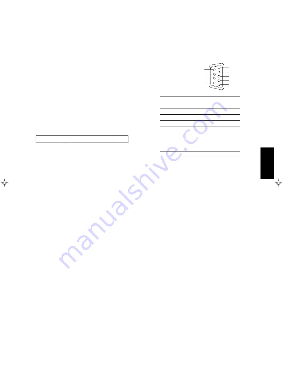
HOW TO USE THE RS-232C TERMINAL

You can control the monitor from your PC via the RS-232C terminal.
For details on operating the monitor from the PC, consult your dealer or service centre for details.

1. Cable

Prepare a straight cable with a D-sub connector (9-pin, female) and a D-sub
connector (9-pin, male)

2. Communications Specifications

Baud Rate

: 4800/9600/19200 (factory pre-set; 4800)

Data Bits

: 8 bits

Parity

: No parity

Stop Bits

: 1

Flow Control : Hardware (RTS/CTS)

3. Commands

Format

Header

ID

Command

Data

CR

Header

!

Control from the PC to the monitor

?

Reference from the PC to the monitor

@

Answer from the monitor to the PC

 ID + C Data

B

Basic command

Characters

00, 01 or No data

D

Command for adjusting the picture size

00 ~ 08

–20 ~ +20 or –31 ~ +31

S

Command for adjusting the picture quality

00 ~ 05

–20 ~ +20

M

Command for selecting the menu item

00 ~ 0E

00, 01, 10, 11

F

Command for selecting the menu item

00 ~ 0A

00, 01

W

Command for adjusting the white balance

00 ~ 05

–256 ~ +255

C

Command for inquiring for the monitor’s status

00

0 ~ 655

During Communication from the PC to the Monitor
The monitor receives the data when DSR remains ON (high) and CTS is set to ON.
During Communication from the Monitor to the PC
The monitor sends the data when both DSR and DCD are set to ON and RTS is set to ON.

Communication Procedures
The following is the communication procedures.

1. Starting the communication

Receives the connection command (!BCN1Cr) from the PC 

[

 Sends the monitor’s status (@BOKCr) to the PC

2. Performing the external control

Receives the control command (!XXXXCr) from the PC 

[

 Sends the monitor’s status (@BOKCr) to the PC

* The monitor repeats these receiving and sending if necessary.

3. Terminating the communication

Receives the termination command (!BCN0Cr) 

[

 Sends the monitor’s status (@BOKCr) to the PC

* After sending the data to the monitor, the PC must first receive the data from the monitor and then send the next command

because the communication is performed in a hand-shake system. If the PC does not receive the status from the monitor after
sending the command, re-send the command.

4

3

2
1

9
8

5

7

6

Pin No.

Signal

1

DCD (Data Carrier Detect)

2

RD (Receive Data)

3

TD (Transmit Data)

4

DTR (Data Terminal Ready)

5

GND (Ground)

6

DSR (Data Set Ready)

7

RTS (Request To Send)

8

CTS (Clear To Send)

9

RI (Ring Indication)

21

 LCT1116-001A(EN)

02.1.29, 2:54 PM

23

Summary of Contents for DT-V1900CG

Page 1: ...OT3 POWER E F INPUT SELECT ESPAÑOL ITALIANO FRANÇAIS DEUTSCH ENGLISH The illustration shows the DT V1900CG with provided wide mask attached Die Abbildung zeigt Modell DT V1900CG mit angebrachtem mitgelieferten Breitformat Vorsatzrahmen L illustration montre le DT V1900CG avec le masque large fourni monté L illustrazione raffigura il DT V1900CG con montata la maschera per visione panoramica fornita...

Page 2: ...er below the Serial No which is located on the rear of the cabinet Retain this information for future reference Serial No Model No DT V1900CG SAFETY PRECAUTIONS 2 CONTROLS AND FEATURES 4 CONTROLS AND FEATURES INPUT CARD OPTIONAL 6 PREPARATION 9 BASIC MENU OPERATIONS MAIN MENU SETUP MENU 11 HOW TO USE MAIN MENU 12 HOW TO USE SETUP MENU 15 HOW TO USE EXTERNAL CONTROL 20 TROUBLESHOOTING 22 SELF CHECK...

Page 3: ...SS Do not use a magnet eraser to degauss the monitor s cathode ray tube from the outside Doing so may distort its aperture grill and cause a malfunction In order to prevent any fatal accidents caused by misoperation or mishandling the monitor be fully aware of all the following precautions WARNINGS To prevent fire or shock hazard do not expose this monitor to rain or moisture Dangerous high voltag...

Page 4: ...mple is shown in the illustration EMC Supplement Europe only This equipment is in conformity with the provisions and protection requirements of the corresponding European Directives This equipment is designed for professional video appliances and can be used in the following environments Controlled EMC environment for example purpose built broadcasting or recording studio and the rural outdoors en...

Page 5: ...s pressed Indications will be shown even when the STATUS DISPLAY setting is OFF 1 8 2 3 4 5 6 7 9 EMBEDDED AUDIO channel switch button Pressing this button switches the input sound channel When the button is pressed the channel is advanced When the button is pressed channel is reversed NOTE The channel indication will display the selected channel when EMBEDDED in the FUNCTION SETTING setup menu is...

Page 6: ... cards installed in SLOT 1 through SLOT 3 A B select the picture from the SLOT 1 input card C D select the picture from the SLOT 2 input card E F select the picture from the SLOT 3 input card 14 MAKE SLOT1 RS 232C SLOT2 SLOT3 MAIN POWER 26 27 28 29 30 Side Panel Refer to pages 6 and 8 for correspondence between the input terminals and the INPUT SELECT buttons Power lamp Unlit The main power is OFF...

Page 7: ...UT IN OUT IN R PR B Y OUT IN VD OUT IN HD CS OUT IN OUT IN AUDIO OUT IN 1 2 3 4 䡵 VIDEO INPUT CARD OPTIONAL IF C01PNG VIDEO1 OUT IN AUDIO2 AUDIO1 OUT IN VIDEO2 OUT Y C IN IN OUT IN EXT SYNC 1 2 3 4 5 䡵 Compatible signal formats 480 60i 576 50i 576 50p 480 60p 720 60p 1035 60i 1080 50i 1080 60i 1080 24psF Video input output terminals Input IN and output OUT terminals for video signals The IN and OU...

Page 8: ...tion terminal of your Multi Format Monitor 1 䡵 Compatible signal formats 480 60i 576 50i 576 50p 2 3 4 䡵 HD SDI INPUT CARD OPTIONAL IF C01HSDG 䡵 Compatible signal formats 720 60p 1035 60i 1080 50i 1080 60i 1080 24psF Output terminal for a selected component serial digital signal Output terminal for a selected digital signal the input displayed on the screen The output signal is cable compensated N...

Page 9: ... IN and output OUT terminals for HD serial digital signals Select HD SDI 1 press INPUT SELECT A C E button Input and output terminals for HD SDI 2 component serial digital signals Input IN and output OUT terminals for HD serial digital signals Select HD SDI 2 press INPUT SELECT B D F button Connection terminal to a Multi Format Monitor Attach to the connection terminal of your Multi Format Monitor...

Page 10: ...ent to the monitor be sure to install the input cards 䡵 ATTACHING THE WIDE MASK A wide mask is provided with the monitor This changes the viewable screen area to the 16 9 aspect ratio The wide mask cannot be attached to the monitor after the monitor is mounted in a rack Mount the wide mask before installing the monitor in a rack 1 Prepare the provided wide mask and 4 screws for attaching 2 Attach ...

Page 11: ...th the case 䡵 ATTACHING THE POWER CORD HOLDER The provided Power Cord Holder prevents accidental disconnection of the AC power cord from the AC inlet The Power Cord Holder consists of two parts a case and cover Press the cover until it clicks Hold until it clicks Caution A different plug shape will result in the case being attached to a different position Check to make sure the plug doesn t pull o...

Page 12: ... an item Press the or buttons to select or adjust the desired item When the desired item has other menus hierarchical menus Press the button to display the lower hierarchical menu To return to the former Menu Screen Press the MENU button MAIN MENU APERTURE CONTROL SLOT CONDITION sub menu POSITION LOWER AREA MARKER OFF AREA MARKER R OFF CENTER MARKER OFF COLOR MATRIX EXIT MENU ENTER SELECT APERTURE...

Page 13: ...NTER SELECT MAIN MENU APERTURE CONTROL SLOT CONDITION sub menu POSITION LOWER COLOR MATRIX EXIT MENU ENTER SELECT MAIN MENU SLOT CONDITION sub menu POSITION LOWER EXIT MENU ENTER SELECT APERTURE CONTROL LEVEL 00 CONTROL FREQ HIGH sub menu reset EXIT MENU ADJUST SELECT SLOT CONDITION INPUT A VIDEO 1 INPUT B VIDEO 2 INPUT C COMPO INPUT D RGB INPUT E NO SLOT INPUT F NO SLOT EXIT MENU COLOR MATRIX SEL...

Page 14: ...ed in each of the input card slots Press the button to display the setting menu illustrated on the right SLOT CONDITION INPUT A VIDEO 1 INPUT B VIDEO 2 INPUT C COMPO INPUT D RGB INPUT E NO SLOT INPUT F NO SLOT EXIT MENU 䡵 ITEM CONTENTS AND ADJUSTMENT RANGE SETTINGS 16 9 4 3 14 9 13 9 APERTURE CONTROL LEVEL 00 CONTROL FREQ HIGH sub menu reset EXIT MENU ADJUST SELECT Items INPUT A INPUT B INPUT C IN...

Page 15: ... actually display the marker the AREA MARKER button on the monitor needs to be pressed so that it is illuminated Centre marker 7 COLOR MATRIX Selects or adjusts the standard of the colour demodulation colour rendering Press the button to display the setting menu illustrated on the right The menu screen when MANUAL is selected The standard setting is set to ITU601 or ITU709 depending on the input s...

Page 16: ...L SIZE POSI ADJ DISTORTION ADJ STATUS DISPLAY CONTROL LOCK ON all reset EXIT MENU ENTER SELECT FUNCTION SETTING COLOR SYSTEM AUTO SYNC SELECT AUTO RUSH DELAY TIME STD TALLY SELECT GREEN REMOTE SYSTEM MAKE EMBEDDED 1G HOUR METER X100h 000 EXIT MENU ADJUST SELECT PICTURE SUB ADJ CONTRAST 00 BRIGHT 00 CHROMA 00 PHASE 00 NTSC SETUP 00 COMPO LEVEL SMPTE sub menu reset EXIT MENU ADJUST SELECT COLOR TEMP...

Page 17: ...IGGER terminal s tally control in the REMOTE external control terminal setup menu For details refer to Page 20 To set the color use TALLY SELECT in the FUNCTION SETTING setup menu or MAKE TRIGGER in the REMOTE external control terminal setup menu For details refer to Page 16 and 20 Item REMOTE SYSTEM Settings MAKE TRIGGER Function Selects the contact system MAKE make contact or TRG trigger contact...

Page 18: ...or COMPO LEVEL NTSC SETUP settings in a single line display The sub menu display varies depending on the selected item Item reset Function Sets the CONTRAST BRIGHT CHROMA PHASE and COMPO LEVEL NTSC SETUP values to factory preset ones COLOR TEMP BAL COLOR TEMP LOW BLUE DRIVE 000 RED DRIVE 000 GREEN CUTOFF 000 BLUE CUTOFF 000 RED CUTOFF 000 sub menu reset EXIT MENU ADJUST SELECT 3 COLOR TEMP BAL Set...

Page 19: ...e as PINCUSHION PIN BALANCE PARAL LELOGRAM TRAPEZOID and ROTATION Function Performs PINCUSHION PIN BALANCE PARALLELOGRAM TRAPEZOID or ROTATION settings in a single line display The sub menu display varies depending on the selected item Item reset Function Sets the PINCUSHION PIN BALANCE PARALLELOGRAM TRAPEZOID and ROTATION values to factory preset ones SIZE POSI ADJ H SIZE 00 H POSITION 00 V SIZE ...

Page 20: ... CONTROL LOCK Settings OFF ON Function Invalidates most of operations on the front panel including menu screen operations OFF Enables normal operations ON Invalidates all operations except the power switch and CONTROL LOCK NOTE While CONTROL LOCK is set to ON attempting to perform any operation except power switch and CONTROL LOCK causes the Control lock on warning to appear on the screen for appr...

Page 21: ...ally lamp Put off Put on 2 INPUT A Changes the input to INPUT A Not change Change 3 INPUT B Changes the input to INPUT B Not change Change 4 INPUT C Changes the input to INPUT C Not change Change 5 INPUT D Changes the input to INPUT D Not change Change 6 INPUT E Changes the input to INPUT E Not change Change 7 INPUT F Changes the input to INPUT F Not change Change 8 COLOR OFF Changes the picture b...

Page 22: ...ion from the PC to the Monitor The monitor receives the data when DSR remains ON high and CTS is set to ON During Communication from the Monitor to the PC The monitor sends the data when both DSR and DCD are set to ON and RTS is set to ON Communication Procedures The following is the communication procedures 1 Starting the communication Receives the connection command BCN1Cr from the PC Sends the ...

Page 23: ...onitor close to a motor transformer or any other device generating a strong magnetic field a fan fluorescent light laser printer another monitor etc Measures Remedy Firmly insert the power plug Turn the main power ON Connect the signal cable firmly Turn on the power of the connected component and set it correctly Select the correct input with the INPUT SELECT buttons Check that the input signal fo...

Page 24: ... of the damper lines that are necessary for composing the monitor These lines are not a malfunction When a bright still image such as a white cloth is displayed for a long period it may appear to be coloured This is due to the structure of the cathode ray tube and will disappear when another image is displayed You may sometimes experience a mild electric shock when you touch the picture tube This ...

Page 25: ...blinking 2 Turn off the main power switch on the back of the monitor 3 Disconnect the Power Cord from the AC outlet 4 Contact your dealer with the information about which indicators are blinking NOTE If you turn on the monitor s power immediately after turning it off or after a short term power failure the self check indicators may blink and no image may be displayed When this happens turn off the...

Page 26: ...using the IF C01COMG D1 serial digital using the IF C01SDG HD serial digital using the IF C01HSDG IF C12HSDG Dimensions Unit mm Front View with the wide mask attached Illustrations and pictures used in this manual have been exaggerated abbreviated or compounded for explanatory purposes only The appearance of the actual product may differ slightly Dimensions and weight are approximate E O E Design ...

Page 27: ...is section explains the usage precautions and connection examples when using the SWITCHED OUT terminal of the SDI HD SDI input card APPENDIX CONNECTION EXAMPLES FOR THE SDI HD SDI INPUT CARD IF C01SDG IF C01HSDG only 䡵 Compliant Signal Formats of Each Input Card Input Signals IF C01PNG IF C01COMG IF C01SDG IF C01HSDG IF C12HSDG NTSC 3 58 MHz R PAL 4 43 MHz R Black and White 50 Hz 60 Hz R 480 60i 5...

Page 28: ... x 2 1 0 V 4 0 V p p 75 Ω The input IN and output OUT terminals are bridge connected Auto termination Y C signal 1 line input only mini DIN 4 pin connector x 1 Y C input has a priority to a VIDEO 2 input Y 1 V p p 75 Ω C 0 286 V NTSC 0 3 V PAL 75 Ω Audio signal 2 lines monaural RCA pin x 4 0 5 V rms high impedance The input IN and output OUT terminals are bridge connected Required slots 1 Power co...

Page 29: ... 1 Power consumption 14 V DC 0 72 A Weight 0 7 kg Dimensions W x H x D 43 mm x 154 5 mm x 200 2 mm 䡵 IF C12HSDG HD SDI INPUT CARD Type HD SDI input card for Multi Format Monitor Inputs Outputs Digital input HD SDI 1 HD SDI 2 2 lines BNC connector x 2 0 8V p p 75 Ω compliant with AES EBU EMBEDDED AUDIO Digital output HD SDI 1 HD SDI 2 2 lines BNC connector X 2 0 8V p p 75 Ω Format HD serial compone...

Page 30: ......

Page 31: ... 2002 VICTOR COMPANY OF JAPAN LIMITED Printed in Japan 0202 Y U VP VICTOR COMPANY OF JAPAN LIMITED DT V1900CG MULTI FORMAT MONITOR ...

Reviews: