16
External Control
7
About the external control
This monitor has three external control terminals.
•
MAKE/TRIGGER termina
l (RJ-45): The following external control systems are available.
(1)
MAKE (make contact) system
: Controls the monitor by short-circuiting the corresponding pin terminal to
the GND pin terminal, or disconnecting (opening) it.
(2)
TRIGGER (trigger) system
: Controls the monitor by sending the pulse signal instantaneously to the
corresponding pin terminal.
☞
“Using the MAKE/TRIGGER system” on page 17
•
RS-485 terminals
(RJ-45): Controls the monitor with the RS-485 system. (
☞
“Using the serial communication”
on page 18)
•
RS-232C terminal
(D-sub 9-pin): Controls the monitor with the RS-232C system. (
☞
“Using the serial
communication” on page 18)
Set the following items of “REMOTE SETTING” in SET-UP MENU according to the external control terminal and
control system (
☞
“SERIAL TYPE”, “PARALLEL TYPE”
on
page 15).
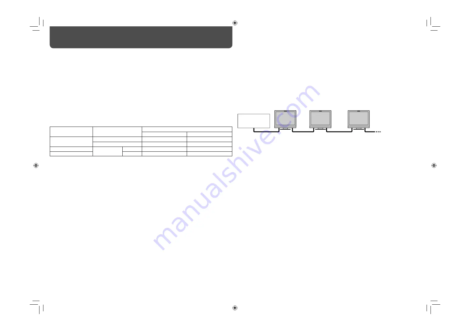
Control terminal
Control system
The settings of this unit
“SERIAL TYPE” setting
“PARALLEL TYPE” setting
MAKE/TRIGGER
terminal
MAKE
—
MAKE
TRIGGER
—
TRIGGER
RS-485 terminal
Serial
communication
RS-485
RS485*
1
—
RS-232C terminal
RS-232C
RS232C*
1
—
*
1
For a monitor connected to a personal computer etc, select the terminal the equipment is actually connected to. For
other monitors, select “RS485.”
PC, etc.
RS-485 IN
or
RS-232C
RS-485
OUT
RS-485
IN
RS-485
OUT
RS-485
IN
RS-485
OUT
Control priority is as follows.
MAKE > TRIGGER = serial communication = buttons and menu on the monitor
• You can use the external control even when “CONTROL LOCK” is set to “ON” (
☞
page 15).
• When the monitor is off (on standby), external control is not available. But certain external controls (starting/
terminating communication, turning on the monitor) are available through the serial communication (
☞
page 18).
<MAKE/TRIGGER system>
You can control the monitor by a personal computer or dedicated controller*
2
.
• For the details, see page 17.
*
2
The controller is not commercially available. Consult your dealer if you need it.
<Serial communication>
• For the details, see page 18.
DT-V17L3REB̲EN.indd 16
DT-V17L3REB̲EN.indd 16
08.9.18 5:27:50 PM
08.9.18 5:27:50 PM