background image

.

PORTABLE CART WARNING
(symbol provided by RETAC)

S3126A

-

-

-

-
-

-
-

-

-

-

-

-

-

IMPORTANT SAFEGUARDS

Electrical energy can perform many useful functions. 
This unit has been engineered and manufactured to 
assure your personal safety. But IMPROPER USE 
CAN RESULT IN POTENTIAL ELECTRICAL 
SHOCK OR FIRE HAZARD. In order not to defeat  
the safeguards incorporated into this product, 
observe the following basic rules for its installation, 
use and service. Please read these Important 
Safeguards carefully before use.

All the safety and operating instructions should be read 
before the product is operated.
The safety and operating instructions should be retained for 
future reference.
All warnings on the product and in the operating 
instructions should be adhered to.
All operating instructions should be followed.
Place the projector near a wall outlet where the plug can be 
easily unplugged.
Unplug this product from the wall outlet before cleaning. 
Do not use liquid cleaners or aerosol cleaners. Use a damp 
cloth for cleaning.
Do not use attachments not recommended by the product 
manufacturer as they may be hazardous.
Do not use this product near water. Do not use immediately 
after moving from a low temperature to high temperature, 
as this causes condensation, which may result in fire, 
electric shock, or other hazards.
Do not place this product on an unstable cart, stand, or 
table. The product may fall, causing serious injury to a child 
or adult, and serious damage to the product. The product 
should be mounted according to the manufacturer’s 
instructions, and should use a mount recommended by the 
manufacturer.
When the product is used on a cart, 
care should be taken to avoid quick 
stops, excessive force, and uneven 
surfaces which may cause the product 
and cart to overturn, damaging 
equipment or causing possible injury to 
the operator.
Slots and openings in the cabinet are 
provided for ventilation. These ensure reliable operation of 
the product and protect it from overheating. These 
openings must not be blocked or covered. (The openings 
should never be blocked by placing the product on bed, 
sofa, rug, or similar surface. It should not be placed in a 
built-in installation such as a bookcase or rack unless 
proper ventilation is provided and the manufacturer’s 
instructions have been adhered to.)
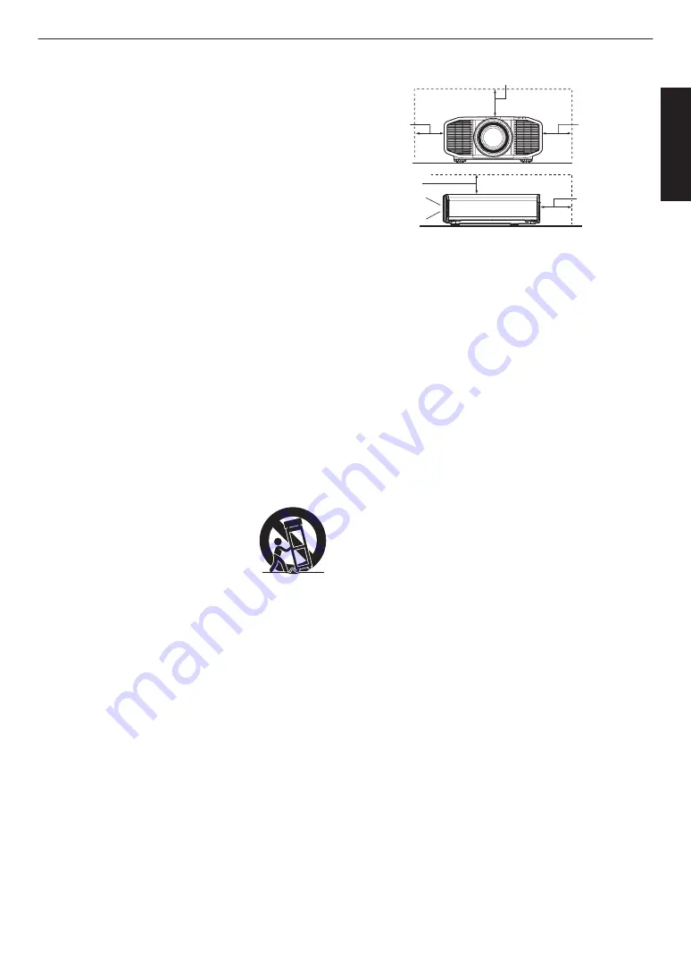
To allow better heat dissipation, keep a clearance between 
this unit and its surrounding as shown below. When this unit 
is enclosed in a space of dimensions as shown below, use 
an air-conditioner so that the internal and external 
temperatures are the same. Overheating can cause 
damage.

-

-

-

-

-

-

-

-

a)
b)

c)
d)

e)

f)

When the power supply cord or plug is damaged.
If liquid has been spilled, or objects have fallen on the 
product.
If the product has been exposed to rain or water.
If the product does not operate normally by following the 
operating instructions. Adjust only those controls that 
are covered by the Operation Manual, as an improper 
adjustment of controls may result in damage and will 
often require extensive work by a qualified technician to 
restore the product to normal operation.
If the product has been dropped or damaged in any 
way.
When the product exhibits a distinct change in 
performance, this indicates a need for service.

Power source indicated on the label. If you are not sure of 
the type of power supply to your home, consult your 
product dealer or local power company.
This product is equipped with a three-wire plug. This plug 
will fit only into a grounded power outlet. If you are unable 
to insert the plug into the outlet, contact your electrician to 
install the proper outlet. Do not defeat the safety purpose of 
the grounded plug.
Power-supply cords should be routed so that they are not 
likely to be walked on or pinched by items placed upon or 
against them. Pay particular attention to cords at doors, 
plugs, receptacles, and the point where they exit from the 
product.
For added protection of this product during a lightning 
storm, or when it is left unattended and unused for long 
periods of time, unplug it from the wall outlet and 
disconnect the cable system. This will prevent damage to 
the product due to lightning and power line surges.
Do not overload wall outlets, extension cords, or 
convenience receptacles on other equipment as this can 
result in a risk of fire or electric shock.
Never push objects of any kind into this product through 
openings as they may touch dangerous voltage points or 
short out parts that could result in a fire or electric shock. 
Never spill liquid of any kind on the product.
Do not attempt to service this product yourself as opening 
or removing covers may expose you to dangerous voltages 
and other hazards. Refer all service to qualified service 
personnel.
Unplug this product from the wall outlet and refer service to 
qualified service personnel under the following conditions:

Front

200 mm 
(8 in) and 
above

300 mm 
(12 in) and 
above

300 mm 
(12 in) and 
above

150 mm (6 in) and above

150 mm 
(6 in) and 
above

3

Getting Started

Summary of Contents for DLA-RS4500 K

Page 1: ...mation comme référence pour le futur Instrucción para el cliente Introduzca a continuación el nº de serie que aparece en la parte inferior lateral de la caja Conserve esta información como referencia para uso ulterior For Customer use Enter below the serial No which is located on the side of the cabinet Retain this information for future reference DLA RS4500 K Model No Serial No DLA RS4500 K N de ...

Page 2: ...e instructions may cause harmful interference to radio communications However there is no guarantee that interference will not occur in a particular installation If this equipment does cause harmful interference to radio or television reception which can be determined by turning the equipment off and on the user is encourage to try to correct the interference by one or more of the following measur...

Page 3: ...wn below When this unit is enclosed in a space of dimensions as shown below use an air conditioner so that the internal and external temperatures are the same Overheating can cause damage a b c d e f When the power supply cord or plug is damaged If liquid has been spilled or objects have fallen on the product If the product has been exposed to rain or water If the product does not operate normally...

Page 4: ...ill images of high brightness or high contrast such as found in video games and computer programs Over a long period of time it might stick to the picture element There is no problem with the playback of moving images e g normal video footage Not using the unit for a long time can lead to malfunction Please power it on and let it run occasionally Please avoid using the unit in a room where cigaret...

Page 5: ...pean representative of JVC KENWOOD Corporation is JVCKENWOOD Deutschland GmbH Konrad Adenauer Allee 1 11 61118 Bad Vilbel Germany THIS APPARATUS MUST BE EARTHED IMPORTANT Europe only The wires in the mains lead on this product are colored Vert et jaune in accordance with the following cord IMPORTANT Europe only POWER CONNECTION United Kingdom only When replacing the fuse be sure to use only a corr...

Page 6: ... cette pile contient du plomb Informatie voor gebruikers over het verwijderen van oude apparatuur en batterijen Alleen Europese Unie Deze symbolen geven aan dat apparatuur met dit symbool niet mag worden weggegooid als algemeen huishoudelijk afval Als u het product of de batterij wilt weggooien kunt u inzamelsystemen of faciliteiten voor een geschikte recycling gebruiken Opmerking Het teken Pb ond...

Page 7: ...s 64 12 W WARNING Beam divergence angle from lens of this unit Laser emission port Wide α 71 Tele α 39 α CAUTION LASER RADIATION AVOID DIRECT EYE EXPOSURE CLASS 32 LASER PRODUCT WAVE LENGTH 453nm MAX OUTPUT 83 56mW RAYONNEMENT LASER EVITER L EXPOSITION DIRECTE DES YEUX PRODUIT LASER DE CLASSE 3R LONGUEUR D ONDE 453nm SORTIE MAX 83 56mW RADIACION LASER EVITAR LAEXPOSICION DIRECTADE LOS OJOS CLASE 3...

Page 8: ...ure For the customers In other countries CLASS 1 LASER PRODUCT Location information of the labels LASER CAUTION LABEL Do not look into the lens while in use WARNING CAUTION LASER CAUTION LABEL IEC62471 5 Location information of the labels As with any bright light source do not stare into the beam RG2 IEC 62471 5 2015 8 Getting Started ...

Page 9: ... the Screen Size Aspect 28 Viewing 3D Movies 29 Installing the 3D SYNCHRO EMITTER 29 Viewing 3D Movies 30 Adjusting 3D Movies 30 Adjust Set Selecting an Image Quality According to the Video Type 31 Setting the Picture Mode 31 Setting the Color Profile 32 Adjusting to the Preferred Color Color Management 34 Adjusting Movies for Increased Detail and Sharpness Multiple Pixel Control 35 Fine tuning th...

Page 10: ...or 0 For details on mounting the badge refer to the instruction manual provided with the badge Optional Accessories 0 3D GLASSES model PK AG3 0 3D SYNCHRO EMITTER model PK EM2 Compatibility Chart for 3D SYNCHRO EMITTER and 3D GLASSES 3D GLASSES PK AG1 Communication Method IR Infrared PK AG2 Communication Method IR Infrared PK AG3 Communication Method RF Radio frequency 3D SYNCHRO EMITTER PK EM1 Co...

Page 11: ...lso a remote sensor at the rear C Indicator Refer to Indicator Display on the Main Unit P 76 D Exhaust vent Warm air is discharged to cool down the internal temperature Do not block the vents Main Unit Bottom E Feet The height and angle of the projector can be adjusted by turning the foot 0 to 5 mm 0 to 0 2 in P 20 When the foot is removed it can be used as the mounting holes for the ceiling mount...

Page 12: ...H Remote Sensor rear Please aim the remote control at this area when using it There is also a remote sensor at the front I Power input terminal Connect the supplied power cord to this terminal J Air Inlets The inlets take in air to cool down the internal temperature Do not block or prevent the outflow of hot air Doing so may cause the unit to malfunction Operation panel MENU Displays the menu BACK...

Page 13: ... projector can be controlled by connecting it to a PC through the computer network for control commands to be sent to the projector E HDMI 1 input terminal F HDMI 2 input terminal For connecting to devices that support HDMI output P 21 It is fitted to the M3 lock hole The depth of the screw hole is 3 mm 0 1 in G TRIGGER terminal Output terminal for DC 12 V 100 mA power supply It is used for sendin...

Page 14: ...ble color profile in sequence Q GAMMA SETTINGS Displays the gamma setting menu R ADVANCED MENU Pressing the button each time switches the menu in the following sequence Picture Mode Color Profile Color Temp Blur Reduction S MPC Displays the MPC setting menu P 35 T C M D For setting frame interpolation P 40 0 Pressing the button each time switches the setting in the following sequence Low High Inve...

Page 15: ...eries can cause battery leakage Effective Range of Remote Control Unit Whenaimingtheremotecontroltowardthesensoronthis unit front or rear ensure that the distance to the sensor is within 7 m If the remote control fails to work properly move closer to this unit 30 30 20 20 Remote Control This unit Control through reflection off a screen etc Ensure that the total of distance A between this unit and ...

Page 16: ...ct the icon at the top of the menu to display its corresponding setting item as shown below A Picture Adjust B Input Signal C Installation D Display Setup E Function F Information A B C D E F 16 Getting Started ...

Page 17: ... path thereby resulting in dark images or dull colors Dirt that sticks to the optical components cannot be removed Maintain clearance from the wall etc As the unit discharges a large amount of heat install it with adequate clearance from the surroundings as shown below Front 200 mm 8 in and above 300 mm 12 in and above 300 mm 12 in and above 150 mm 6 in and above 150 mm 6 in and above Leave the fr...

Page 18: ...r use install it horizontally 0 Make sure to secure the main unit to prevent accidents such as during an earthquake Securing with screws 4 Locations Remove the four feet at the bottom and fasten using the screws M5 screws 15 to 25 mm Using screws other than those designated may cause the unit to break down 18 Set up ...

Page 19: ... 0N m Tightening with torque exceeding the above range may cause damage to the unit which may result the unit to fall 0 When reusing the ceiling mount bracket of an old model consult the specialist to check if there are any issues with the surrounding space and increase in weight 0 Install the outlet at an accessible height to unplug from the wall Or install the circuit breaker at an accessible he...

Page 20: ...on Æ Adjusting the Lens According to the Projection Position P 26 Up to about 100 of the projected image Horizontal Position 0 Center Vertical Position Up to about 43 of the projected image Vertical Position 0 Center Horizontal Position 16 9 image 120 100 80 60 40 20 0 10 30 20 40 50 Amount of horizontal shift Amount of vertical shift Lens shift Range 0 The maximum vertical shift varies with the a...

Page 21: ...HDMI 2 EDID P 49 0 Some cables cannot be connected to this unit due to the size of their connector cover Connecting to the HDMI Input Terminal Digital Input Connecting via HDMI cable HDMI Output Terminal BD DVD Recorder etc Laptop etc HDMI Cable Sold Separately This Unit To HDMI 1 or HDMI 2 input terminal 0 If noise occurs move the laptop away from this unit Connecting through an AV amplifier HDMI...

Page 22: ...To LAN Terminal 0 The network is used to control this unit It is not used for sending or receiving video signals 0 Please contact your network administrator for information concerning the network connection 0 Set ECO Mode to Off if LAN communication is performed in the Standby mode P 58 0 For more information on control please refer to External Control P 67 Connecting to the RS 232C Terminal RS 23...

Page 23: ... 58 Connecting the Power Cord Supplied Accessory A Connect the power cord supplied to the power input terminal on the main unit B Insert the supplied power plug into the wall outlet Precautions to prevent fire and electric shock 0 The power consumption of this unit is large Please connect it directly to the wall outlet 0 When you are not using the projector please unplug the power cord from the ou...

Page 24: ...fter the unit starts up LIGHT WARNING STANDBY ON LIGHT WARNING STANDBY ON LIGHT WARNING STANDBY ON DB AN BY O DB AN BY O When in ECO Mode STANDBY ON light off When LD block is starting up STANDBY ON lights up green In standby state STANDBY ON lights up red 2 Choose the image to project Remote control press the HDMI 1 or HDMI 2 button Projector unit press the INPUT button to switch the input 0 Play...

Page 25: ...0 After about 10 seconds the STANDBY ON indicator switches from a blinking red to a solid red light LIGHT WARNING STANDBY ON DB TAN Y O LIGHT WARNING STANDBY ON DB In standby state STANDBY ON lights up red In the Cool down mode STANDBY ON blinking red 0 Attach the lens cover CAUTION 0 The power cannot be turned off within approximately 30 seconds after it has been turned on 0 The power cannot be t...

Page 26: ... mode in the following sequence Focus Zoom Shift Focus 0 Operation of the lens control feature is disabled when the lens lock is set to On 0 For more detailed information please refer to Lens Control P 51 Shift Screen Position Adjustment Zoom Screen Size Adjustment ABCD ABCD ABCD Focus Adjustment 2 Press the MENU button once or the BACK twice to end adjustment SETTING MEMORY MODE 1 MODE 2 MODE 3 A...

Page 27: ... 0 This item is not available when Color Profile is set to Off 0 For information on the screen and the corresponding correction mode please visit our website http www3 jvckenwood com english projector screen MEMO 0 You can utilize the optional optical sensor and dedicated projector calibration software to make finer adjustments For details on the dedicated projector calibration software please vis...

Page 28: ...age horizontally to the maximum while maintaining its aspect ratio for display Part of the image that runs off the edge vertically will not be displayed Auto Magnifies the input image horizontally or vertically to the maximum while maintaining its aspect ratio for display Native Any image below 1920x1080 and 2048x1080 will be scaled 4 times the native resolution of the source Any source above 1920...

Page 29: ...efer to Optional Accessories P 10 Installing the 3D SYNCHRO EMITTER 1 Connect 3D SYNCHRO EMITTER to the 3D SYNCHRO terminal on the main unit Installation Example 3D GLASSES 3D SYNCHRO EMITTER PK EM2 This Unit PK AG3 CAUTION 0 If PK EM1 is used adjust the position of the 3D SYNCHRO EMITTER such that the 3D GLASSES can receive the signal from the 3D SYNCHRO EMITTER For more details please refer to t...

Page 30: ...cognized as 3D ones If a signal cannot be displayed as 3D image selecting the format does not switch the signal to a 3D image For more information on possible input signals please refer to Types of Possible Input Signals P 75 In the default setting 3D Format is set to Auto for automatic projection of 3D images 2 Turn of the power of the 3D GLASSES and put them on 0 The PK AG1 powers on automatical...

Page 31: ...t focuses on natural color and gradation reproduction Suitable for drama footage etc Cinema Reproduces the image in vivid colors Suitable for all movies HDR 1 Making full use of the wide color gamut and contrast this mode is suited for viewing HDR contents such as Ultra HD Blu ray Film Reproduces faithfully the texture of movie films THX 2 Image quality certified by THX User 1 to User 6 Enables us...

Page 32: ...CI Anime Color space that is suitable for CG animation works Ideal for animated works with bright colors Cinema Original JVC cinema specific color gamut that achieves a balance between increased brightness and color vividness HDR Color space suitable for HDR content Film 1 Color space that is close to the characteristics of Eastman Kodak Company movie films Film 2 Color space that is close to the ...

Page 33: ...re Mode Picture Mode Color Profile Natural BT 709 BT 2020 DCI Anime HDR Cinema BT 709 BT 2020 Cinema DCI HDR HDR HDR BT 2020 BT 709 DCI Film Film 1 Film 2 THX THX User 1 to User 6 BT 709 BT 2020 DCI Anime Cinema HDR Off Custom1 to Custom6 33 Adjust Set ...

Page 34: ...of the central axis of the selected color Hue 30 to 30 Adjusts the hue color tone Saturation 30 to 30 Adjusts the color saturation vividness 30 dull to 30 vivid Brightness 30 to 30 Adjusts the brightness 30 dark to 30 bright 0 Selecting Reset resets all the adjustment data 0 Pressing the HIDE button on the remote control enables you to check the image before adjustment Press the HIDE button again ...

Page 35: ... on the setting of the selected Picture Mode The factory setting varies with the Picture Mode Item Setting Description Graphic Mode 4K 2K For selecting whether the content you are viewing is of high sharpness such as graphics It is recommended to set to 4K when viewing content mastered in 4K Enhance 0 to 10 Enhances the sharpness of the image Smoothing 0 to 10 Enhances the blurriness of the image ...

Page 36: ...Input Value Output Value A B A B Increases the contrast with respect to the original image creating a greater sense of depth 0 255 0 255 A B A B The photos are for illustrative purposes only Input Value Output Value 1 Press the GAMMA button 0 Pressing the GAMMA button each time switches the setting in sequence 0 You can also perform the setting by pressing the MENU button to display the menu follo...

Page 37: ... to 2 2 2 4 and 2 6 respectively 2 4 2 6 Cinema 1 Places emphasis on the gradation Cinema 2 Places emphasis on the contrast HDR ST 2084 Suited for viewing HDR content such as UHD BD HDR10 HDR Hybrid Log Suited for viewing HDR content such as HDR broadcast and streaming sources THX Video of the THX standard Custom 1 to Custom 3 Enables fine adjustment of gamma according to preference Selectable Gam...

Page 38: ...ect to 16 brightens image for an overexposed effect Dark Level Adjusts the dark areas of the input image 0 To do so use the H I keys to move the cursor 7 darkens the shadows to 7 brightens the shadows Bright Level Adjusts the bright areas of the input image 0 To do so use the H I keys to move the cursor 7 darkens the highlights to 7 brightens the highlights Selecting the Base Correction Value Init...

Page 39: ...t 0 When the gamma curve is a straight line The brightness and contrast of the video input will be the same as that of the video output 0 Area for which the gamma curve is above the straight line A Video output appears brighter than the input 0 Area for which the gamma curve is below the straight line B Video output appears darker than the input 0 Area for which the slope of the gamma curve is ste...

Page 40: ...ts 3D images For some scenes interpolation may cause distortion in the image that supports 3D images In this case set to Off Intermediate Frame Generation Intermediate Frame Generation Interpolation Enabled Original Image 1 Press the C M D button 0 Pressing the C M D button each time switches the mode in the following sequence Off Low High Inverse Telecine Off Setting Description Off Interpolation...

Page 41: ...the liquid crystal device If the image outline is unnatural set this item to Off 1 Press the MENU button to display the menu and select Picture Adjust Blur Reduction Motion Enhance Setting Description Off Does not perform correction Low Reduces image blurring High Further reduces image blurring than Low 41 Adjust Set ...

Page 42: ... Mode P 31 9 Dynamic CTRL P 44 9 LD Power P 44 9 Aperture P 44 9 User Name Edit P 44 I Color Profile P 32 9 Color Management P 34 I Color Temp P 45 I Gamma P 36 9 Picture Tone P 38 9 Dark Level Bright Level P 38 I MPC Level P 35 I Blur Reduction P 40 I Contrast P 48 I Brightness P 48 I Color P 48 I Tint P 48 Input Signal I Input Level P 49 I Color Space P 49 I Aspect P 49 I 3D Setting P 29 IHDMI 2...

Page 43: ... Pixel P 52 9 Adjust Fine P 52 9 Reset P 52 I Mask P 56 I Anamorphic P 56 I Screen Adjust P 27 I Installation Style P 56 I Keystone P 56 I Pincushion P 57 I High Altitude Mode P 57 Display Setup I Back Color P 57 I Menu Position P 57 I Signal Display P 57 I Logo P 57 I Language P 57 Function I Trigger P 58 I Off Timer P 58 I ECO Mode P 58 I Network P 59 I Remote Code P 59 I Hide Mode P 59 I Factor...

Page 44: ... range of video expression Stronger control than Mode 1 LD Power For changing the brightness through controlling the output Setting Description Low Brightness low Mid Brightness mid High Brightness high Aperture For changing the brightness through controlling the aperture 0 Setting range 15 stops down to 0 opens up User Name Edit You can edit the User 1 to User 6 names in the Picture mode 0 Charac...

Page 45: ...vary according to Picture Mode Color Temp Color Temp Description Xenon 1 Color temperature that reproduces the characteristics of a xenon lamp used in cinemas 0 Xenon 1 A light source color that is emitted by a film projector 0 Xenon 2 A light source color emitted by a projector used for digital cinema Xenon 2 5500K Increasing the value enhances the blue tone of the video image while decreasing th...

Page 46: ...ture Mode Color Temp Film Xenon 1 Xenon 2 Custom 1 to Custom 2 Cinema 5500K 6500K 7500K 9300K Xenon 1 Xenon 2 High Bright HDR Custom 1 to Custom 2 Natural HDR User 1 to User 6 5500K 6500K 7500K 9300K High Bright HDR Custom 1 to Custom 2 THX 6500K 46 Adjust Set ...

Page 47: ...e table below List of selectable Correction Value according to Picture Mode Picture Mode Correction Value Film Xenon 1 Xenon 2 Cinema Xenon 1 Xenon 2 5500K 6500K 7500K 9300K High Bright Natural HDR User 1 to User 6 5500K 6500K 7500K 9300K High Bright Gamma You can adjust the output value of the projected image with respect to the video signal input Æ Adjusting the Output Value of the Projected Ima...

Page 48: ...riness of the image for a softer effect 0 Setting range 0 to 10 NR Prevents noise from becoming too pronounced 0 Setting range 0 weak to 10 strong Blur Reduction For reducing the after image which occurs in a fast moving scene Æ Reducing the After image of Fast moving Images Blur Reduction P 40 Contrast For adjusting the white level point to avoid clipping or over saturation 0 Setting range 50 lit...

Page 49: ...electing Auto select an appropriate setting Setting Description Auto Detects YCbCr444 YCbCr422 and RGB automatically YCbCr444 Select this setting when inputting YCbCr 4 4 4 video signals YCbCr422 Select this setting when inputting YCbCr 4 2 2 video signals RGB Select this setting when inputting RGB video signals Aspect The screen size of the projected image can be adjusted optimally according to t...

Page 50: ...ase numeric characters and symbols 0 Enter not more than 10 characters y l Y L x k X K 0 w j W J 9 v i V I 8 y h U H 7 t g T G 6 s f S F 5 r e R E 4 q d Q D 3 p c P C 2 o b O B z M Z m 1 n a N A Name Mode 1 After entry is complete select OK and press the OK button Selection Cursor Input Cursor OK All Clear Clear Space Name Edit Mode Copy For copying the setting values managed by the current Instal...

Page 51: ...plays external signals and does not display the lens adjustment pattern Lock For setting whether to lock or unlock the lens Setting to On to lock the lens allows you to preserve the adjustment status of the lens Setting Description On Locks the lens to prevent any erroneous operation on the adjustments 0 When On is selected all lens control functions other than Lens Memory Select cannot be operate...

Page 52: ... of the color selected in Adjust Color Æ Whole Adjust Pixel Operation Procedure P 53 0 Adjustment cannot be made when Adjust Area is set to Zone Setting Description H Horizontal Setting range 2 moves red blue to the left to 2 moves red blue to the right V Vertical Setting range 2 moves red blue downward to 2 moves red blue upward Adjust Fine When Adjust Area is set to Whole adjustment can be made ...

Page 53: ...cal and horizontal pixels of the entire zone 0 The adjustment setting appears at the center of the Adjustment Pixel window Color A BACK GAMMA Adjust Color P A Area COLOR TEMP 3D FORMAT PIC ADJ H 0 V 0 Red Pixel Adjust Back Whole Adjust Pixel Remote Control Operation Guide Color for Adjustment Pixel Adjustment Setting E After adjustment is complete press the BACK button twice to exit the Adjustment...

Page 54: ...of the entire zone 0 The adjustment setting appears at the center of the Fine window H 20 20 20 V 5 5 5 0 0 0 0 0 0 V H Red Whole Adjust Fine Pixel Adjust Color A BACK GAMMA Adjust Color P A Area COLOR TEMP 3D FORMAT PIC ADJ Back Indicates the maximum and minimum misalignment value of the entire screen Max Min Adjustment Setting Remote Control Operation Guide Color for Adjustment Pixel Adjustment ...

Page 55: ...Zone Adjustment Window Zone Cursor Adjustment Pattern Red Color A BACK GAMMA Adjust Color P A Area COLOR TEMP 3D FORMAT PIC ADJ Back 0 0 0 0 V H Position Zone Adjust Pixel Adjust D Press the JKH I keys to move the cursor to the point to be adjusted E Press the OK button to enter the Adjustment mode F Use the JKH I keys to move and adjust the vertical and horizontal pixels of the entire zone 0 The ...

Page 56: ...only Screen Adjust By selecting the optimal correction mode according to the characteristics of the screen in use corrections can be performed to reproduce natural images with balanced colors Æ Setting Screen Correction P 27 Installation Style For setting to Front Ceiling Mount F Rear or Ceiling Mount R according to the installation status of the projector 0 Front or Ceiling Mount F is set when pr...

Page 57: ...ackground to Blue or Black when there is no signal input Menu Position For setting the display position of the menu Signal Display For setting the display of the input information to On or Off Setting Description On Shows the input terminal for 5 seconds when input is switched Off Not displayed Logo For setting the display of logo during startup to On or Off Setting Description On Displays the D I...

Page 58: ...y when the projector is not operated 0 Setting values Off 1 Hour 2 Hours 3 Hours and 4 Hours ECO Mode Setting Description On Enables ECO Mode to minimize power consumption in the Standby mode 0 RS 232C LAN communication cannot be used in the Standby mode 0 If there is no signal transmission and operation for 20 minutes while an image is projected the power management switches the equipment automat...

Page 59: ...ress that is a segment of the IP address Default Gateway Server for communicating beyond the network that is divided by the subnet mask MAC Address Abbreviation for Media Access Control address This is a number that is unique to each network adapter Each of the network adapters is assigned with a unique MAC address Remote Code For changing the remote control code Setting Description A Change the r...

Page 60: ...signalinput Displays the input source Resolution Displayed only during PC signal input Displays the image resolution H Frequency Displays the horizontal frequency V Frequency Displays the vertical frequency Color Depth Displays the color bit depth of the input video signal 0 Not displayed when YCbCr 4 2 2 is input 0 Displayed when Deep Color information is received from the source device Color Spa...

Page 61: ...e unit may also appear as shadows on the image 2 3 4 1 Sponge Filter Gray Air Filter White 1 Loosen the 4 screws and remove the cover 0 The screws cannot be removed from the cover Do not try to remove the screws from the cover by force 2 Remove the sponge filter 3 Use a vacuum cleaner to remove dirt from the sponge filter carefully 4 Restore the sponge filter 5 Restore the cover and fasten the 4 s...

Page 62: ...n the power again When High Altitude Mode is set to On and LD Power is set to High during 3D mode the fan will make louder noise than usual since it is designed to run at high speed in 3D mode Power is not supplied Check Action Refer to Is the power cord disconnected Insert the power cord plug firmly P 23 Is the unit in the Cool down mode After exiting the Cool down mode turn on the power again P ...

Page 63: ...in the case of 3D video images P 30 Is an intermediate device AV amplifier divider etc in use Connect the source device to the projector directly and check whether there is any improvement in the condition If the condition improves it is likely that this is not caused by malfunction of the projector P 21 Is the cable in use an HDMI certified cable Use an HDMI certified high speed cable Also use as...

Page 64: ... placed too near or too far away from the screen Set the unit at a correct distance from the screen P 73 Video image flickers Check Action Refer to Do you see horizontally extended overlapping video images In this case set 3D Format to Auto P 30 Are you viewing the video images under a fluorescent light This is caused by interference between the 3D glasses with the flickers of the fluorescent ligh...

Page 65: ...use P 15 Are the IR infrared 3D GLASSES and 3D SYNCHRO EMITTER in use As there is a possibility of signal interference when you are using the IR infrared 3D GLASSES together with the 3D SYNCHRO EMITTER try adjusting the orientation of the 3D SYNCHRO EMITTER P 29 Noise is heard Check Action Refer to Is the exhaust vent blocked Is the unit used near a heater or air conditioner Check the installation...

Page 66: ...ut terminal 0 The input terminal is connected but there is no signal Input the video signals HDMI 1 A video signal that cannot be used with this unit has been input The names of input terminals such as HDMI 1 and HDMI 2 will be displayed in yellow Input video signals that can be used P 75 66 Troubleshooting ...

Page 67: ... Non synchronous Character length 8 bit Parity None Start bit 1 Stop bit 1 Data rate 19200 bps Data format Binary 1 5 6 9 This Unit D6 D7 D4 D5 D2 D3 D0 D1 Stop bit Start bit TCP IP Connection Before controlling via LAN it is necessary to establish connection of the TCP layer by a 3 way handshake followed bysendingout PJREQ andreceiving PJACK withinfivesecondsaftertheprojectorsendsout PJ_OK forcon...

Page 68: ... command and data binary code Command Type Description 0000 Connection check Check whether communication is enabledbetweenthisunitandthe PC during standby 5057 Power supply During standby 31 Turns on the power When power is on 30 Turns off the power Standby mode 4950 Input When power is on 36 HDMI 1 37 HDMI 2 5243 Remote control Sends the same code as the supplied remote control 0 Remote Control C...

Page 69: ... 37 33 44 39 MODE 3 37 33 44 41 LENS CONTROL 37 33 33 30 LENS AP 37 33 32 30 ANAMO 37 33 43 35 HIDE 37 33 31 44 J 37 33 30 31 K 37 33 30 32 I 37 33 33 34 H 37 33 33 36 Remote Control Button Name Binary Code OK 37 33 32 46 MENU 37 33 32 45 BACK 37 33 30 33 NATURAL 37 33 36 41 CINEMA 37 33 36 38 HDR 37 33 45 44 PICTURE MODE 37 33 46 34 COLOR PROFILE 37 33 38 38 GAMMA SETTINGS 37 33 46 35 MPC 37 33 4...

Page 70: ...0 57 0A When power is turned off Standby mode from power on mode Remote control MENU PC This unit 21 89 01 52 43 37 33 32 45 0A This unit PC 06 89 01 52 43 0A When the same operation as pressing the MENU button on the remote control is performed Reference command Type Command Description Power On PC This unit 3F 89 01 50 57 0A This unit PC 06 89 01 50 57 0A This unit PC 40 89 01 50 57 31 0A When i...

Page 71: ...rature 5 C to 35 C humidity 20 to 80 storage temperature 10 C to 60 C Installation Height Below 5 000 ft 1524 m Dimensions Width x Height x Depth 500 mm x 235 mm x 720 mm 19 685 in x 9 25 in x 28 3 in including feet Mass 37 5 kg 82 7lb Accessories Refer to P 10 1 D ILA is the abbreviation for Direct Drive Image Light Amplifier 2 D ILA devices are manufactured using extremely high precision technol...

Page 72: ... and high resolution which is granted to products that have cleared more than 400 image quality tests This unit is isf certified so calibration can be performed by an isf certified trainer After calibration is performed an isf mode is added to the Picture mode For more details please refer to the isf website http www imagingscience com About Trademarks and Copyrights HDMI HDMI logo and High Defini...

Page 73: ... 7 53 3 90 7 92 4 12 8 36 4 79 9 71 140 3 99 8 11 4 20 8 53 4 44 9 01 5 16 10 46 150 4 28 8 70 4 51 9 15 4 76 9 66 5 53 11 21 160 4 58 9 28 4 81 9 76 5 09 10 31 5 91 11 96 170 4 87 9 87 5 12 10 38 5 41 10 96 6 28 12 72 180 5 16 10 45 5 43 10 99 5 73 11 61 6 66 13 47 190 5 45 11 04 5 73 11 61 6 05 12 26 7 03 14 22 200 5 74 11 62 6 04 12 22 6 38 12 91 7 41 14 98 210 6 03 12 21 6 34 12 84 6 70 13 56 ...

Page 74: ...70 31 84 140 13 10 26 62 13 78 27 99 14 57 29 57 16 93 34 31 150 14 06 28 54 14 79 30 01 15 63 31 70 18 16 36 78 160 15 01 30 46 15 79 32 03 16 69 33 83 19 39 39 25 170 15 97 32 38 16 80 34 04 17 75 35 96 20 61 41 72 180 16 92 34 30 17 80 36 06 18 81 38 09 21 84 44 19 190 17 88 36 22 18 80 38 08 19 86 40 22 23 07 46 66 200 18 83 38 14 19 81 40 10 20 92 42 35 24 30 49 13 210 19 79 40 06 20 81 42 12...

Page 75: ...GA 800 600 37 879 60 317 40 000 1056 628 800 600 XGA 1024 768 48 363 60 004 65 000 1344 806 1024 768 WXGA 1280 768 47 776 59 870 79 500 1664 798 1280 768 WXGA 1280 800 49 702 59 810 83 500 1680 831 1280 800 FWXGA 1366 768 47 712 59 790 85 500 1792 798 1366 768 WXGA 1440 900 55 935 59 887 106 500 1904 934 1440 900 SXGA 1280 1024 63 981 60 020 108 000 1688 1066 1280 1024 WXGA 1600 900 60 000 60 000 ...

Page 76: ...ector unit LIGHT STANDBY ON WARNING LIGHT STANDBY ON WARNING LIGHT STANDBY ON WARNING LIGHT STANDBY ON WARNING LIGHT STANDBY ON WARNING DB TAN BY O DB TAN BY O D D Y O A ANDBY O When in ECO Mode When the video image is temporarily hidden HIDE is on During projection All lights off In the Cool down mode STANDBY ON blinking red When LD block is starting up STANDBY ON lights up green In standby state...

Page 77: ...G Red Mode Display x2 Cooling fan stopped abnormally 0 Check that nothing is blocking the air inlets 0 Check that the external temperature is normal Countermeasure Leave the unit unoperated until it cools down After that turn on the power again x3 Internal temperature is abnormally high x4 External temperature is too high LIGHT STANDBY ON WARNING N N NG WA LIGHT Blinking Simultaneously Red Orange ...

Page 78: ...720 28 3 17 0 7 500 19 7 Front 235 9 3 127 5 0 66 2 6 20 0 8 205 8 1 133 5 2 133 5 2 110 4 3 Bottom Surface Ø 6 0 2 4 37 1 5 41 1 6 58 2 3 91 3 6 290 11 4 440 17 3 560 22 0 337 13 3 Rear Surface 175 6 9 157 6 2 22 0 9 130 5 1 78 Others ...

Page 79: ...I Color Space 49 HDMI Input Level 49 HDMI Input Terminal 21 HIDE 24 High Altitude Mode 57 I Indicator Display 76 INFO 14 Input Resolution 60 75 Input Signal 60 75 Input terminals 13 Installation Method 17 Installing the 3D Syncro Emitter 29 K Keystone Correction 56 L Language Selection 57 Lens 11 LENS AP 14 Lens Control 26 Lens Cover 10 Lens Memory 26 Lens Shift 26 Line Display 57 Logo Display 57 ...

Page 80: ...me Edit 44 V Viewing 3D Movies 29 Viewing Videos 24 W When the following messages appear 66 Z Zoom 26 Symbol 3D Crosstalk Cancel 30 3D Format 30 3D Glasses 10 29 3D Setting 49 3D Synchro Emitter 10 29 80 Others ...

Page 81: ... 81 Others ...

Page 82: ... 82 Others ...

Page 83: ... 83 Others ...

Page 84: ... DLA RS4500 D ILA PROJECTOR 2016 JVCKENWOOD Corporation 1116KSY SW IT ...

Reviews: