2-4
UX-G6/FS-G6
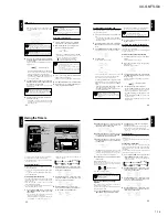
Removing the regulator board
(See Fig.10)
•
Prior to performing the following procedure,
remove the top cover.
1. Disconnect the card wire from connector CN908
on the main board.
2. Disconnect the harness from connector CN906
on the main board.
3. Remove the two screws G attaching the regula-
tor board.
Removing the transformer assembly
(See Fig.11)
•
Prior to performing the following procedure,
remove the top cover.
1. Disconnect the harness from connector CN904,
CN905 and CN903 on the main board.
2. Remove the four screws H attaching the trans-
former assembly.
3. Remove the cord stopper and the voltage selec-
tor as shown in Fig.9.
(If necessary, unsolder the soldered point and cut
off the belt fixing the harness.)
Fig. 10
Fig. 11
G
G
Regulator board
Main board
CN908
CN906
H
H
CN905
CN903
CN904
Cord stopper
Voltage selector
Power transformer
Summary of Contents for AX-UXG6
Page 16: ...1 16 UX G6 FS G6 M E M O ...
Page 17: ...2 1 UX G6 FS G6 AX UXG6 ...
Page 27: ...2 11 UX G6 FS G6 XT UXG6 ...
Page 46: ...2 30 UX G6 FS G6 M E M O ...
Page 47: ...2 31 UX G6 FS G6 TD UXG6 ...
Page 65: ...2 49 UX G6 FS G6 A B C D E F G 3 4 5 2 1 FL Display and micom section AX UXG6 ...
Page 66: ...2 50 UX G6 FS G6 A B C D E F G 3 4 5 2 1 System control section XT UXG6 Main signal ...
Page 68: ...2 52 UX G6 FS G6 A B C D E F G 3 4 5 2 1 Tuner section XT UXG6 except Ver J FM Tuner signal ...
Page 69: ...2 53 UX G6 FS G6 A B C D E F G 3 4 5 2 1 Tuner section XT UXG6 only Ver J FM Tuner signal ...
Page 73: ...2 57 UX G6 FS G6 A B C D E F G 3 4 5 2 1 System control Analog IN digital OUT board XT UXG6 ...
Page 74: ...2 58 UX G6 FS G6 A B C D E F G 3 4 5 2 1 CD Servo Main board XT UXG6 ...
Page 75: ...2 59 UX G6 FS G6 A B C D E F G 3 4 5 2 1 Main board TD UXG6 ...
Page 76: ...2 60 UX G6 FS G6 A B C D E F G 3 4 5 2 1 Tuner board TD UXG6 ...
Page 85: ...3 9 UX G6 FS G6 M E M O ...

