background image

AV-N29304
AV-N29430

1-6 (No.52129)

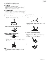
2.5 DISASSEMBLY PROCEDURE

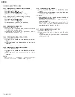
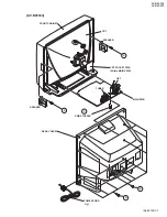
2.5.1 REMOVING THE REAR COVER [AV-N29304]

(1) Unplug the power plug.
(2) Remove the 11 screws 

[A]

 (Fig.1).

(3) Remove the 4 screws 

[B]

 (Fig.1).

(4) Then remove the REAR COVER toward you.

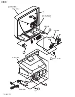
2.5.2 REMOVING THE REAR COVER [AV-N29430]

(1) Unplug the power plug.
(2) Remove the 7 screws 

[A]

 (Fig.2).

(3) Remove the 4 screws 

[B]

 (Fig.2).

(4) Then remove the REAR COVER toward you.

2.5.3 REMOVING THE MAIN PWB

• Remove the REAR COVER.

(1) Raise this side of the MAIN PWB, and remove the PWB

STOPPER 

[C]

 from the cabinet.

(2) Withdraw the MAIN PWB backward. (If necessary, remove

the wire clamp, connectors etc.)

2.5.4 REMOVING THE SPEAKER [AV-N29304]

• Remove the REAR COVER.

(1) Remove the 4 screws 

[D]

, then remove the speaker

(Fig.1).

(2) Follow the same steps when remove the other hand

speaker.

2.5.5 REMOVING THE SPEAKER [AV-N29430]

• Remove the REAR COVER.

(1) Remove the 4 screws 

[D]

, then remove the speaker

(Fig.2).

(2) Follow the same steps when remove the other hand

speaker.

NOTE:

When removing the 4 screws 

[D]

 of the speaker, remove the

lower side screw first, and then remove the upper one.

2.5.6 CHECKING THE PW BOARD

(1) Pull out the MAIN PWB (refer to REMOVING THE MAIN

PWB).

(2) Erect the MAIN PWB vertically so that you can easily check

the backside of the PW Board.

CAUTION:

• When erecting the chassis, be careful so that there will be no

contacting with other PW Board.

• Before turning on power, make sure that the wire connector

is properly connected.

• When conducting a check with power supplied, be sure to

confirm that the CRT EARTH WIRE (BRAIDED ASS'Y) is
connected to the CRT SOCKET PW board.

2.5.7 WIRE CLAMPING AND CABLE TYING

(1) Be sure to clamp the wire.
(2) Never remove the cable tie used for tying the wires

together.
Should it be inadvertently removed, be sure to tie the wires
with a new cable tie.

Summary of Contents for AV-N29304

Page 1: ...N LTD No 52129 2003 04 AV N29304 AV N29430 COLOR TELEVISION 52129 2003 04 AV N29304 RA AV N29304 SA AV N29430 RA AV N29430 SA TABLE OF CONTENTS 1 PRECAUTIONS 1 3 2 SPECIFIC SERVICE INSTRUCTIONS 1 4 3 ADJUSTMENT 1 12 AV N29304 AV N29430 BASIC CHASSIS FE2 ...

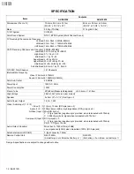
Page 2: ...te Frequency Video IF Carrier Sound IF Carrier 45 75MHz 41 25MHz 4 5MHz Color Sub Carrier 3 58MHz Power Input 120V AC 60Hz Power Consumption 105W Picture Tube 29 68cm Measured diagonally H 55 4cm x V 41 8cm High Voltage 28kV 1 3kV at zero beam current Speaker 5 x 9cm 2 x 3 1 2 Oval type x 2 Audio Power Output 1 2W 1 2W Video Audio Input 1 2 3 Video 1 3 Audio 1 2 3 S Video Input 1 Component Input 2...

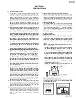
Page 3: ...ves approved by the manufacturer of the complete product 8 Do not check high voltage by drawing an arc Use a high voltage meter or a high voltage probe with a VTVM Discharge the picture tube before attempting meter connection by connecting a clip lead to the ground frame and connecting the other end of the lead through a 10kΩ 2W resistor to the anode button 9 When service is required observe the o...

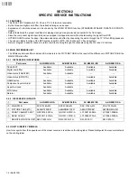
Page 4: ...ifference in PICTURE TUBE the MAIN PWB also differ 2 2 1 DIFFERENCE IN FEATURES 2 2 2 DIFFERENCE IN PARTS 2 3 HOW TO IDENTIFY MODELS How to recognize from the appearance of the model concerned is written on the rating label Please distinguish from several contents on the printing label Part name AV N29304 RA AV N29304 SA AV N29430 RA AV N29430 SA TELE TEXT Available Available Available Available D...

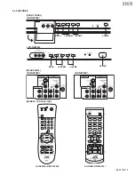
Page 5: ... AV N29430 No 52129 1 5 2 4 FUNCTIONS REAR PANEL REMOTE CONTROL UNIT FRONT PANEL MENU POWER POWER CHANNEL VOLUME MENU CHANNEL VOLUME AV N29304 RM C1255G AV N29430 RM C203 AV N29304 AV N29304 AV N29430 AV N29430 ...

Page 6: ...REMOVING THE SPEAKER AV N29430 Remove the REAR COVER 1 Remove the 4 screws D then remove the speaker Fig 2 2 Follow the same steps when remove the other hand speaker NOTE When removing the 4 screws D of the speaker remove the lower side screw first and then remove the upper one 2 5 6 CHECKING THE PW BOARD 1 Pull out the MAIN PWB refer to REMOVING THE MAIN PWB 2 Erect the MAIN PWB vertically so tha...

Page 7: ...AV N29304 AV N29430 No 52129 1 7 Fig 1 AV N29304 A B D C D FRONT CABINET CRT SPEAKER CRT SOCKET PWB Within MAIN PWB MAIN PWB PWB STOPPER SPEAKER REAR COVER POWER CORD TUNER HVT ...

Page 8: ...AV N29304 AV N29430 1 8 No 52129 Fig 2 FRONT CABINET CRT SOCKET PWB Within MAIN PWB TUNER HVT B A D D MAIN PWB SPEAKER PWB STOPPER REAR COVER C CRT POWER CORD AV N29430 ...

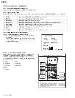
Page 9: ... the power on 4 Setting of receive channels Set the receive channels For setting refer to the OPERATING INSTRUCTIONS 5 User settings Check the user setting items according to USER SETTING VALUES and if these are different set the correct value 6 SERVICE MENU setting Verify what to set in the SERVICE MENU and set whatever is necessary Refer to the SERVICE ADJUSTMENT for setting 1 V C S 3 SOUND A 7 ...

Page 10: ...G OF MENU PICTURE MODE INITIAL SETUP MODE TINT Center LANGUAGE SPA COLOR Center FRONT PANELLOCK OFF PICTURE 8 V2 COMPONENT IN NO BRIGHT Center AUTO SHUT OFF OFF DETAIL 10 CLOSED CAPTION OFF NOISE MUTING ON AUTO TUNER SET UP AIR SOUND MODE CHANNEL SUMMARY Unnecessary to set BASS Center SET LOCK CODE 0000 Unnecessary to set TREBLE Center XDS ID ON BALANCE Center MTS STEREO CLOCK TIMERS MODE SET CLOC...

Page 11: ...ift with the tweezers and remove the chip part Transistors diodes variable resistors etc 1 Apply extra solder to each lead 2 As shown in the figure push the part with tweezers and alternately melt the solder at each lead Shift and remove the chip part Note After removing the part remove remaining solder from the pattern 2 How to install Chip parts Resistors capacitors etc 1 Apply solder to the pat...

Page 12: ...s for warning up for at least 30 minutes before starting adjustments 5 If the receive or input signal is not specified use the most appropriate signal for adjustment 6 Never touch the parts such as variable resistors transformers and condensers not shown in the adjustment items of this service adjustment 7 Preparation for adjustment Unless otherwise specified in the adjustment items preset the fol...

Page 13: ...ATIONS CRT SOCKET PWB Within MAIN PWB ASS Y T TP E SOLDER SIDE TOP CRT EARTH BRAIDED ASS Y E1 TP B MAIN PWB POWER FRONT HV UPPER FOCUS LOWER SCREEN X TUNER MEMORY IC201 IC702 IC421 HVT S AV IN OUT VOL VOL CH CH MENU POWER B1 IC901 F901 U IC101 T111 S401 ...

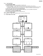
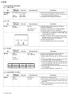
Page 14: ... yellow 1 V C S This mode adjusts the VIDEO and CHROMA control circuit 2 DEF D This mode adjusts the DEFLECTION control circuit 3 SOUND A This mode adjusts the SOUND control circuit 4 OTHERS F This mode adjusts the display setting and the other settings Do not change the values 7 LOW LIGHT This mode adjusts the WHITE BALANCE LOW LIGHT control circuit 8 HIGH LIGHT This mode adjusts the WHITE BALANC...

Page 15: ...ode is peculiar please refer to the clause of the ADJUSTMENT PROCEDURE 4 OTHERS AND 11 I2C BUS ADJUSTMENT MODE These are no requirement for adjustment Don t change these values 3 4 3 4 Release of SERVICE MENU When adjustment is completed press the EXIT key twice Then return to the normal screen 3 4 4 SERVICE MENU FLOW CHART 1 V C S RF 4 3 STD LOW S01 BRIGHT RF 4 3 STD LOW D01 V FREQ BRIGHT 2 DEF D...

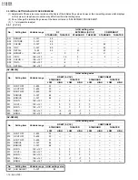
Page 16: ...5 0 0 S08 COLOR 128 127 3 1 S09 TINT 128 127 6 3 S10 DETAIL 128 127 3 No Setting item Variable range Initial setting value RF EXT SV CV COMPONENT STANDARD THEATER STANDARD THEATER LOW HIGH LOW HIGH LOW HIGH LOW HIGH S11 R CUT OFF 0 255 30 S12 G CUT OFF 0 255 30 S13 B CUT OFF 0 255 30 S14 R DRIVE 0 127 64 S15 B DRIVE 0 127 64 S16 R CUT 128 127 0 0 0 0 S17 G CUT 128 127 0 0 0 0 S18 B CUT 128 127 0 0...

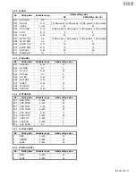
Page 17: ...BTM 0 31 16 16 D11 EW PARA 0 63 26 26 D12 BLANK SW 0 1 0 0 No Setting item Variable range Initial setting value A01 IN LEVEL 0 63 17 A02 FH MON 0 1 0 A03 ST VCO 0 63 36 A04 PIL CAN 0 1 0 A05 FILTER 0 63 35 A06 LOW SEP 0 63 7 A07 HI SEP 0 63 18 A08 5FH MON 0 1 0 A09 SAP VCO 0 63 37 No Setting item Variable range Initial setting value F01 OSD POSI 0 255 22 F02 OSD PREQ 0 255 83 F03 CCD POSI 0 63 42 ...

Page 18: ... be done in this statement 6 It return the AFC to ON 7 Push the EXIT key to exit the 9 VCO mode TOO HIGH GOOD TOO LOW SYNC YES AFC ON FINE 0 Item Measuring instrument Test point Adjustment part Description RF AGC Signal generator Remote control unit 1 V C S S21 AGC ADJ 1 Receive a black and white signal colour off 2 Select S21 AGC ADJ of the 1 V C S 3 Press the MUTING key and turn the picture colo...

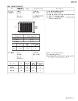
Page 19: ... Adjust the V CENTER SW to agree the vertical center with display center H CENTER Signal generator Remote control unit 2 DEF D D02 H POSI 1 Receive the crosshatch signal 2 Select D02 H POSI 3 Adjust the D02 so that left width and right width of the crosshatch screen becomes equal Picture size 100 Screen size No D03 Setting item V SIZE 0㨪125 Variable range Initial setting value 40 RA model SA model...

Page 20: ...e single horizontal line that is displayed becomes white using the 4 to 9 keys 8 Turn the SCREEN VR until the single horizontal line is displayed faintly 9 Press the 2 key to cancel the single horizontal line mode 10 Adjust the S01 level to become the black component shines white slightly by VOLUME key 11 Confirm that whether the color ingredient of R G or B is visible to the black component which...

Page 21: ...01 with the VOLUME key 4 If the brightness is not the best with the initial setting value make fine adjustment of the S01 until you get the optimum brightness SUB CONTRAST Remote control unit 1 V C S S02 PICTURE 1 Receive the broadcast 2 Select S02 PICTURE of the 1 V C S 3 Set the initial setting value of the S02 with the VOLUME key 4 If the contrast is not the best with the initial setting value ...

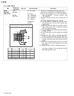
Page 22: ... the S03 until you get the optimum color Method of adjustment using measuring instrument 1 Receive the full field color bar signal 75 white 2 Select S03 COLOR of the 1 V C S 3 Set the initial setting value of the S03 with the VOLUME key 4 Connect the oscilloscope between TP B and TP E 5 Adjust S03 and bring the value of A in the illustration to the voltage given in the below table Item Measuring i...

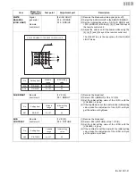
Page 23: ...the S04 until you get the optimum tint Method of adjustment using measuring instrument 1 Receive the full field color bar signal 75 white 2 Select S04 TINT of the 1 V C 3 Set the initial setting value of the S04 with the VOLUME key 4 Connect the oscilloscope between TP B and TP E 5 Adjust S04 and bring the value of B in the illustration to the voltage given in the below table Item Measuring instru...

Page 24: ...terminal 2 Connect an oscilloscope to R OUT pin of the AUDIO OUT and display one cycle portion of the 300Hz signal 3 Select the A06 LOW SEP of the SOUND MODE 4 Set the initial setting value of the A06 with the VOLUME key 5 Adjust the A06 so that the stroke element of the 300Hz signal will become minimum 6 Change the connection of the oscilloscope to L OUT pin of the AUDIO OUT and enlarge the volta...

Page 25: ...HECKING OF THE HIGH VOLTAGE HOLD DOWN CIRCUIT 1 Turn the power switch to on 2 Refer to the following figure set the resistor between X connector 1 and 3 3 Make sure that the screen picture disappears 4 Temporarily unplug the power plug 5 Remove the resistor replaced X connector 1 and 3 6 Again plug the power plug make sure that the normal picture is displayed on the screen T521 CONNECTOR RESISTOR ...

Page 26: ... No 52129 AV MULTIMEDIA COMPANY DISPLAY CATEGORY 12 3 chome Moriya cho kanagawa ku Yokohama kanagawa prefecture 221 8528 Japan VICTOR COMPANY OF JAPAN LIMITED Printed in Japan AV N29304 AV N29430 ...

Reviews: