background image

No. 51914

AV-48WP30

3

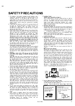
SAFETY PRECAUTIONS

1.  The design of this product contains special hardware, many

circuits and components specially for safety purposes. For
continued protection, no changes should be made to the
original design unless authorized in writing by the manufacturer.
Replacement parts must be identical to those used in the
original circuits. Service should be performed by qualified
personnel only.

2.  Alterations of the design or circuitry of the products should not

be made. Any design alterations or additions will void the
manufacturer's warranty and will further relieve the
manufacturer of responsibility for personal injury or property
damage resulting therefrom.

3.  Many electrical and mechanical parts in the products have

special safety-related characteristics. These characteristics are
often not evident from visual inspection nor can the protection
afforded by them necessarily be obtained by using
replacement components rated for higher voltage, wattage, etc.
Replacement parts that have these special safety
characteristics are identified in the parts list of Service manual.

Electrical components having such features are identified
by shading on the schematics and by (

!

!

!

!

) on the parts list

in Service manual.

 The use of a substitute replacement which

does not have the same safety characteristics as the
recommended replacement part shown in the parts list of
Service manual may cause shock, fire, or other hazards.

4. 

Use isolation transformer when hot chassis.

The chassis and any sub-chassis contained in some products
are connected to one side of the AC power line. An isolation
transformer of adequate capacity should be inserted between
the product and the AC power supply point while performing
any service on some products when the HOT chassis is
exposed.

5. 

Don't short between the LIVE side ground and ISOLATED

(NEUTRAL) side ground or EARTH side ground when
repairing.

Some model's power circuit is partly different in the GND. The
difference of the GND is shown by the LIVE : (

"

) side GND,

the ISOLATED(NEUTRAL) : (

#

) side GND and EARTH : (

$

)

side GND. Don't short between the LIVE side GND and
ISOLATED(NEUTRAL) side GND or EARTH side GND and
never measure with a measuring apparatus (oscilloscope etc.)
the LIVE side GND and ISOLATED(NEUTRAL) side GND or
EARTH side GND at the same time.
If above note will not be kept, a fuse or any parts will be broken.

6.  If any repair has been made to the chassis, it is recommended

that the B1 setting should be checked or adjusted (See
ADJUSTMENT OF B1 POWER SUPPLY).

7.  The high voltage applied to the picture tube must conform with

that specified in Service manual. Excessive high voltage can
cause an increase in X-Ray emission, arcing and possible
component damage, therefore operation under excessive high
voltage conditions should be kept to a minimum, or should be
prevented. If severe arcing occurs, remove the AC power
immediately and determine the cause by visual inspection
(incorrect installation, cracked or melted high voltage harness,
poor soldering, etc.). To maintain the proper minimum level of
soft X-Ray emission, components in the high voltage circuitry
including the picture tube must be the exact replacements or
alternatives approved by the manufacturer of the complete
product.

8.  Do not check high voltage by drawing an arc. Use a high

voltage meter or a high voltage probe with a VTVM. Discharge
the picture tube before attempting meter connection, by
connecting a clip lead to the ground frame and connecting the
other end of the lead through a 10k

Ω

  2W resistor to the anode

button.

9.  When service is required, observe the original lead dress.

Extra precaution should be given to assure correct lead dress
in the high voltage circuit area. Where a short circuit has
occurred, those components that indicate evidence of
overheating should be replaced. Always use the
manufacturer's replacement components.

10. 

Isolation Check

(Safety for Electrical Shock Hazard)

After re-assembling the product, always perform an isolation
check on the exposed metal parts of the cabinet (antenna
terminals, video/audio input and output terminals, Control
knobs, metal cabinet, screwheads, earphone jack, control
shafts, etc.) to be sure the product is safe to operate without
danger of electrical shock.

(1) 

Dielectric Strength Test

The isolation between the AC primary circuit and all metal parts
exposed to the user, particularly any exposed metal part having
a return path to the chassis should withstand a voltage of
1100V AC (r.m.s.) for a period of one second.
(. . . . Withstand a voltage of 1100V AC (r.m.s.) to an appliance
rated up to 120V, and 3000V AC (r.m.s.) to an appliance rated
200V or more, for a period of one second.)
This method of test requires test equipment not generally found
in the service trade.

(2) 

Leakage Current Check

Plug the AC line cord directly into the AC outlet (do not use a
line isolation transformer during this check.). Using a "Leakage
Current Tester", measure the leakage current from each
exposed metal part of the cabinet, particularly any exposed
metal part having a return path to the chassis, to a known good
earth ground (water pipe, etc.). Any leakage current must not
exceed 0.5mA AC (r.m.s.).
However, in tropical area, this must not exceed 0.2mA AC
(r.m.s.).

"

"

"

"

 Alternate Check Method

Plug the AC line cord directly into the AC outlet (do not use a
line isolation transformer during this check.). Use an AC
voltmeter having 1000 ohms per volt or more sensitivity in the
following manner. Connect a 1500

Ω

 10W resistor paralleled

by a 0.15

μ

F AC-type capacitor between an exposed metal

part and a known good earth ground (water pipe, etc.).
Measure the AC voltage across the resistor with the AC
voltmeter. Move the resistor connection to each exposed metal
part, particularly any exposed metal part having a return path to
the chassis, and measure the AC voltage across the resistor.
Now, reverse the plug in the AC outlet and repeat each
measurement. Any voltage measured must not exceed 0.75V
AC (r.m.s.).    This corresponds to 0.5mA AC (r.m.s.).
However, in tropical area, this must not exceed 0.3V AC
(r.m.s.).    This corresponds to 0.2mA AC (r.m.s.).

0.15

μ

F  AC-TYPE

1500

Ω

 10W

GOOD
EARTH
GROUND

PLACE THIS PROBE
ON EACH EXPOSED
METAL PART

AC VOLTMETER
(HAVING 1000

Ω

/V,

OR MORE SENSITIVITY)

11. 

High voltage hold down circuit check.

After repair of the high voltage hold down circuit, this circuit
shall be checked to operate correctly.
See item "

How to check the high voltage hold down

circuit

".

A         V

This mark shows a fast
operating fuse, the
letters indicated below
show the rating.

POWER CORD
REPLACEMENT WARNING.

Connecting the white line side of power
cord to “WHT” character side.

Summary of Contents for AV-48WP30

Page 1: ......

Page 2: ... 2 SAFETY PRECAUTIONS 3 FEATURES 4 FUNCTIONS 4 INSTALLATION 7 TECHNICAL INFORMATION 8 MAIN PARTS LOCATION 9 SPECIFIC SERVICE INSTRUCTIONS 10 SERVICE ADJUSTMENTS 19 TROUBLESHOOTING 51 PARTS LIST 53 OPERATING INSTRUCTIONS STANDARD CIRCUIT DIAGRAM 2 1 SERVICE MANUAL REAR PROJECTION TELEVISION BASIC CHASSIS SB2 ...

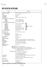
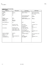
Page 3: ... Screen Screen Size Projection Tube High Voltage Transparent screen unitized fresnel lens double lenticular lens 48 122cm Measured diagonally 16 9 ratio W 106 3cm H 59 8cm 17cm 6 7 tube 3 R G B 31kV 1 0kV at zero beam current Speaker Audio Power Output φ13cm round 2 φ5 5cm round 2 10W 10W External Input Video Input Audio Input 1Vp p 75Ω RCA pin jack 4 500mVrms 4dBs high impedance RCA pin jack 8 S ...

Page 4: ...ved by the manufacturer of the complete product 8 Do not check high voltage by drawing an arc Use a high voltage meter or a high voltage probe with a VTVM Discharge the picture tube before attempting meter connection by connecting a clip lead to the ground frame and connecting the other end of the lead through a 10kΩ 2W resistor to the anode button 9 When service is required observe the original l...

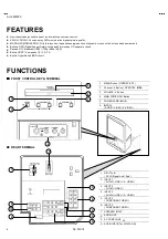
Page 5: ...ive DTV broadcast 1080i 720p 480p 480i Built in HDCP Component Y PB PR Built in Hyper Sound BBE circuit FUNCTIONS FRONT CONTROL KEY TERMINAL REAR TERMINAL 6 2 1 3 5 4 7 2 1 3 4 5 6 8 1 MENU Button OPERATE 2 Channel Button OPERATE 3 VOLUME Button 4 MAIN POWER SW Button 5 POWER LAMP BLUE 6 INPUT4 AUDIO VIDEO S VIDEO 1 DIGITAL IN DVI D Signal Link 19pin 2 INPUT 1 AUDIO VIDEO S VIDEO 3 INPUT 2 AUDIO V...

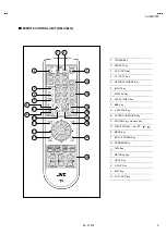
Page 6: ... CINEMA Key 6 INPUT Key 7 DISPLAY Key 8 SLEEP TIMER Key 9 BBE Key A V STATUS Key B HYPER SURROUND Key C MUTING Key memory Key D FUNCTION Key E MENU Key F MULTI SCREEN Key G NUMBERS Key H 100 Key I RETURN Key J LIGHT Key K V CHIP Key L EXIT Key M VCR DVD Key 4 5 6 7 17 9 10 12 13 14 3 2 1 15 16 18 8 19 11 20 21 22 ...

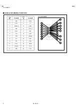
Page 7: ...T 9 10 11 12 13 1 2 3 4 5 6 7 8 17 18 19 20 21 22 23 24 14 15 16 PIN No PIN NAME PIN No PIN NAME 1 RX2 13 RX3 2 RX2 14 5V 3 GND2 4 15 GND 4 RX4 16 HTPLG 5 RX4 17 RX0 6 SCL 18 RX0 7 SDA 19 GND0 5 8 NC 20 RX5 9 RX1 21 RX5 10 RX1 22 GNDC 11 GND1 3 23 TXC 12 RX3 24 TXC ...

Page 8: ...key the convergence adjustment screen appears with crosses displayed in 9 locations Locations where the crosses appear in 3 colours Convergence adjustment is required Perform steps 4 to 5 Locations where the crosses are white The convergence is adjusted correctly lf all the crosses are white no convergence adjustment is needed 4 The locations of the crosses correspond to the positions of the numbe...

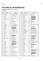
Page 9: ...IN_CCD I I I I For main CCD 39 VREFHS I I I I STD VOL in for CCD 40 CLH I I I I For main CCD 41 VDD O O O O 3 3V 42 LED_DATA O O O O Front control Data PIN PIN NAME I O I O I O I O FUNCTION 43 LED_CLOCK O O O O F LED CLK 44 LED_ON_TIMER O O O O LED on timer 45 SBO0 46 SBD0 47 AP DATA 48 INC 49 ECO RST O O O O Eco Reset 50 ROT COIL L O O O O Picture rotation 51 ROT COIL R O O O O Picture rotation 5...

Page 10: ... PWB ASS Y SSB0H051A M2 G VM PWB ASS Y SSB 7251A M2 I P CONVERT MODULE PWB ASS Y SSB0D051A M2 B VM PWB ASS Y SSB 7351A M2 FRONT I F PWB ASS Y SSB0L251A M2 FRONT CONTROL PWB ASS Y SSB0L051A M2 AV JACK PWB ASS Y SSB0J051A M2 REMOCON SENSOR PWB ASS Y SSB 8051A M2 RECEIVER PWB ASS Y SSB0R251A M2 DIGITAL INPUT MODULE PWB ASS Y SSB 7851A M2 DIGITAL CONVERGENCE MOULE PWB FRONT CONTROL PWB CONVERGENCE PWB...

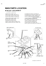
Page 11: ...oves all three projection units DISASSEMBLY CAUTION The projection units include locations that are not to be disassembled during service When replacing projection unit parts disassemble to the state indicated in the figure below The figure indicates screws and wires that are not to be removed Use care not to remove these DISASSEMBLY PROCEDURE If the screen or screen panel need to be replaced remo...

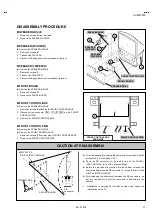
Page 12: ...ve the SPEAKER GRILLE Remove the FRONT CONTROL BOX 1 Remove 3 screws F from rear side of FRONT CONTROL BOX 2 Remove the FRONT CONTROL PWB FRONT CONTROL PWB BH X R BG FRONT CONTROL BOX REAR SIDE SPEAKER GRILL C D A E FRONT CONTROL BOX FRONT BOARD SPEAKER WIRE A B SPEAKER WOOFER SPEAKER TWEETER SB connector POWER CORD Prior to disassembly unplug the power code from the AC outlet without fail Turn th...

Page 13: ...rror from the hooks 3 Remove the MIRROR NOTE The MIRROR is front coated Do not touch the front of the MIRROR At least 2 persons are recommended for removable and reassemble REAR PANEL 1 Loosen 7 screws J 2 Remove 4 screws K 3 Raise slightly REAR PANEL upward 4 Remove the REAR PANEL NOTE Before the rear panel is inserted into the cabinet release the short circuit between the SB connector 1 pin and ...

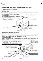
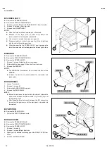
Page 14: ...rying the main unit use care not to drop shock or shake it Do not stain or damage the lens of the projection unit Do not look through the projection unit CHECKING THE P W BOARD When checking the MAIN PWB POWER DEF PWB etc raise the MAIN UNIT with the DIVIDER side down for the sake of convenience You can checking the MAIN P W B LINE FILTER P W BOARD Remove the REAR PANEL Remove the AV JACK BOARD 1 ...

Page 15: ...ove the REAR PANEL 1 Remove 1 screws T attaching the DIVIDER 2 Remove the HV DIVIDER Wires of the transformer FBT and CRT of each PROJECTION UNIT can be removed by turning the connector portions NOTE If necessary remove the anode wires and replacing the HV DIVIDER take care to correctly engage the U connector AV JACK BOARD Remove the REAR PANEL 1 Remove 7 screws V 2 Pull out the POWER CORD CLAMP f...

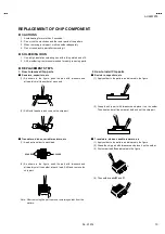
Page 16: ...rs and remove the chip part Transistors diodes variable resistors etc 1 Apply extra solder to each lead 2 As shown in the figure push the part with tweezers and alternately melt the solder at each lead Shift and remove the chip part Note After removing the part remove remaining solder from the pattern 2 How to install Chip parts Resistors capacitors etc 1 Apply solder to the pattern as indicated i...

Page 17: ...ey and VIDEO STATUS key on the remote control unit Fig 2 simultaneously 2 The SERVICE MENU screen of Fig 1 is displayed 3 Verify what to set in the SERVICE MENU and set whatever is necessary Fig 1 Refer to the SERVICE ADJUSTMENT for setting 4 Press the EXIT key twice to return normal screen 5 Receive channel setting Refer to the OPERATING INSTRUCTIONS USER S GUIDE and set the receive channels Chan...

Page 18: ...0 00 00 00 00 THATER 00 00 00 00 00 DYNAMIC 00 00 2 00 00 CHANNEL SETTING CHANNEL SUMMARY BAND CH Display Setting BAND CH Display Setting 02 N 27 03 O 28 04 P 29 05 Q 30 VHFL 06 R 31 07 S 32 08 T 33 09 U 34 10 V 35 11 SUPER W 36 12 A 7 93 VHFH 13 A 6 394 14 A 5 95 36 A 4 96 41 A 3 97 46 A 2 98 63 A 1 99 UHF 69 SUBMID A 8 01 A 14 W 11 47 B 15 W 12 48 C 16 W 17 53 D 17 E 18 W 23 59 F 19 HYPER G 20 W...

Page 19: ...UTING BASS TREBLE BALANCE ON CENTER HYPER SURROUND OFF MTS STEREO SET CLOCK ON OFF TIMER LANGUAGE CLOSED CAPTION FRONT PANEL LOCK Unnecessary to set NO ENG OFF CC1 T1 OFF SPLIT SOURCE POP SOURCE LEFT SIDE CH 02 RIGHT SIDE CH 04 LEFT SIDE CH 02 RIGHT UPPER CH 04 RIGHT CENTER CH 05 RIGHT BOTTOM CH 07 VERTICAL POSITION CENTER CH INPUT XDS ID CONVERGENCE POWER INDICATOR CENTER OFF ON OPTIMUM CONDITION...

Page 20: ... adjustment 7 Presetting before adjustment Unless otherwise specified in the adjustment instructions preset the following functions with the remote control unit SETTING POSITION ADJUSTMENT EQUIPMENT 1 DC voltmeter or digital voltmeter 2 Oscilloscope 3 Signal generator Pattern generator NTSC 480i 480p 720p 1080i HDCP 4 Remote control unit 5 TV audio multiplex signal generator 6 Frequency counter AD...

Page 21: ...ONVERGENCE MODULE PWB FRONT CONTROL PWB LED POWER POWER SW CH CH VOL VOL MENU BG R X BH INPUT 3 G H FRONT I F PWB G H TUNER TU101 CPU E AV JACK PWB CN007 DC SY Q2 AJ CN006 S2 F F B CN001 CN002 CN003 B J S1 LINE FILTER PWB POWER CORD CONVERGENCE OSD PWB AF FRONT 1 5 1Pin L 2Pin R 3Pin GND 4Pin SOA 5Pin NC CN010 BG BH SERVICE SWITCH CN00M P AJ DIGITAL INPUT PWB DIGITAL INPUT PWB G VM PWB R G B CRT S...

Page 22: ...PWB SG001 KR SG001 KG SG001 KB MEMORY IC IC703 IC701 POWER DEF PWB H CPU E CN001 CN002 CN003 B J S1 CN010 DEF OSC PWB MAIN PWB A AB RHV GHV BHV FBT 1 5 5 1 5Pin TP 91 B1 4Pin NC 3Pin X ray1 2Pin X ray2 1Pin TP E LINE FILTER PWB DC Q SY IC SB CONNECTOR DIGITAL INPUT MODULE PWB FOCUS PACK REAR TOP TOP DVI D terminal S1 MAIN PWB AV JACK PWB G VM PWB ...

Page 23: ... press DISPLAY key and VIDEO STATUS key on the remote control unit simultaneously to enter the SERVICE MENU screen as shown in the fig 1 2 SERVICE MENU screen selection Press the number key to select any of the following items 1 PICTURE SOUND 7 I2C BUS 2 YC SEP 8 PP 3 LOW LIGHT 9 IP 4 HIGH LIGHT 0 SELF CHK 5 RF AFC 3 Enter the any setting mode 1 PICTURE SOUND mode 1 Select the 1 PICTURE SOUND item...

Page 24: ...RF AFC 6 7 I2C BUS 8 PP 9 IP 0 SELF CHK NTSC PIP LOW Press the 0 key ON OFF DO NOT ADJUST YC001 YC007 DO NOT ADJUST PPA001 008 PPB001 036 PPC001 007 ADM001 034 ADS001 034 VCM001 038 VCS001 041 IPA001 120 IPB001 088 IPC001 044 IPD001 058 IPE001 015 DO NOT ADJUST Function key Function key F01 D01 S01 A01 F01 F64 A01 A16 S01 S57 D01 D20 Press the 0 key ON OFF AIO LOB SYNC MEM VCD AIO TUN PP NG2 OK M ...

Page 25: ...RE SOUND SETTING VALUE DO NOT ADJUST NTSC FULL DYNAMIC LOW SIGNAL SYSTEM ASPECT SIZE WHITE BALANCE VIDEO STATUS SETTING A01 A16 S01 S57 ITEM D01 D20 F01 F64 YC001 2 YC SEP SETTING VALUE SETTING ITEM YC001 YC107 LW BAL 3 LOW LIGHT Setting Value SETTING ITEM B CUT OFF VALUE G CUT OFF VALUE R CUT OFF VALUE HW BAL 4 HIGH LIGHT Setting Value SETTING ITEM Setting Value B DRIVE VALUE R DRIVE VALUE TUNER ...

Page 26: ...AY Press 0 key of remote control that checks the circuit operating status and in event of malfunction displays stores the data in memory shown in figure PPA001 8 PP SETTING ITEM SETTING VALUE PPA001 PPA008 PPB001 PPB036 PPC001 PPC007 ADM001 ADM034 IPA001 9 IP SETTING ITEM SETTING VALUE IPA001 IPA120 IPB001 IPA088 IPC001 IPC044 IPD001 IPD058 IPE001 IPE015 NTSC PIP OFF FRAM 0 SELF CHK DO NOT ADJUST ...

Page 27: ...REBLE 128 127 000 A07 LOW SEP 0 63 027 A15 BASS 128 127 012 A08 HI SEP 0 63 028 A16 TREBLE 128 127 008 DEFLECTION SYSTEM Item No Item name Variable range Initial setting value Item No Item name Variable range Initial setting value D01 V HEIGHT 0 127 027 D11 H EHT 0 7 001 D02 EW PARABORA 0 63 022 D12 EHT GAIN 0 7 002 D03 H WIDTH 0 63 051 D13 ADJUSTMENT 0 15 000 D04 V S CORR 0 63 040 D14 H CENTER 0 ...

Page 28: ...SUB BRIGHT 0 255 134 133 134 133 S04 SUB CONTRAST 0 127 079 045 079 045 S05 SUB BRIGHT OFFSET 128 127 S06 SUB CONTRAST OFFSET 128 127 480p 720p 1080i HDCP 2 2 480p 720p 1080i HDCP SPLIT FREEZE Item No Item name Variable range Standard Theater Standard Theater Standard Theater S03 SUB BRIGHT 0 255 132 134 S04 SUB CONTRAST 0 127 082 047 S05 SUB BRIGHT OFFSET 128 127 000 000 000 000 S06 CUB CONTRAST ...

Page 29: ... S13 B DRIVE OFFSET 128 127 000 000 000 000 006 000 000 008 HDCP 3 3 HDCP Standard Theater Item No Item name Variable range High Low High Low S10 R DRIVE 0 255 S11 R DRIVE OFFSET 128 127 004 000 000 005 S12 B DRIVE 0 255 S13 B DRIVE OFFSET 128 127 005 000 010 023 NTSC 480i 480p 720p 1080i NTSC 480i 480p 720p 1080i HDCP Item No Item name Variable range Standard Theater Standard Theater Standard The...

Page 30: ... LINK 0 1 000 000 S33 BLACK GRADIATION CORRECTION OFF 0 1 000 001 S34 WHITE GRADIATION CORRECTION OFF 0 1 000 001 NTSC 480i 480p 720p 1080i HDCP HDCP Item No Item name Variable range NTSC 480i 480p 720p 1080i 480p 720p 1080i S35 TINT HD NTSC 0 1 001 001 001 001 001 Item No Item name Variable range Standard Theater S36 ABL OFF 0 1 000 000 S37 ACL OFF 0 1 000 000 S38 DC TRANSMIT POLARITY 0 1 001 000...

Page 31: ... 480i OTHERS SIGNAL S46 EE THEATER BRIGHT 128 127 000 000 000 S47 EE THEATER CONTRAST 128 127 000 000 000 ALL SIGNAL Item No Item name Variable range Setting value S48 BRIGHT EE CONT CORRECTION 0 31 008 S49 REFRAIN EE CONT CORRECTION 0 31 027 S50 REFRAIN EE BRIGH OFFSET CORR MAX 0 127 004 S51 BRIGHT EE ACL CORR COEFF 0 255 085 S52 REFRAIN EE ACL CORR COEFF 0 255 140 S53 No use 0 1 000 S54 No use 0...

Page 32: ...ADJUST 4 0 15 005 F43 POWER OFF WHITE 0 1 000 F13 AUTO SCROLL ADJUST 5 0 15 006 F44 WHITE BACK ON OFF 0 1 000 F14 AUTO SCROLL ADJUST 6 0 15 007 F45 F15 AUTO SCROLL ADJUST 7 0 15 007 F46 F16 Not use 0 1 000 F47 F17 Not use 0 1 000 F48 F18 Not use 0 1 000 F49 F19 Not use 0 1 000 F53 S N RF CORR WIDTH 0 255 000 F20 Not use 0 1 000 F54 S N RF CORR START 0 255 000 F21 Not use 0 1 000 F55 S N BS CORR WI...

Page 33: ...VEL 0 3 000 002 002 002 002 F51 CLAMP PLUS 0 1 000 000 000 000 000 F52 HD PHASE 0 63 038 035 026 039 024 2 2 Setting Value Item No Item name Variable Range HDCP 480p SIZE 1 HDCP 480p SIZE 2 HDCP720p HDCP1080i F50 SEP LEVEL 0 3 002 002 002 002 F51 CLAMP PLUS 0 1 000 000 000 000 F52 HD PHASE 0 63 042 017 047 044 ...

Page 34: ...a white black signal 2 Connect the high voltage meter between CRT anode and GND 3 Check that the High Voltage DC 31 0kV 1 0kV X RAY PROTECTOR check Resistor 6 8kΩ Ω Ω Ω1 6W 5 S1 connector 2 pin X Ray2 3 pin X Ray1 1 Connect resistor 6 8kΩ 1 6W 5 between 2 2 pin 3 pin of the connector S1 3 Confirm that the X RAY protector functions operated H FREQUENCY check Signal generator Remote control unit D15...

Page 35: ...fference of the focus is big it removes a main lens and it puts a washer between the main lens and the coupler and it adjusts it BEAM SPOT 8 Receive a dot pattern signal 9 Makes a red single color NOTE When making a single color It squeezes SCREEN VR in each one or it does a lid to the lens in of the adjustment color and it makes it single color 10 Turn the R FOCUS VR to set the dot diameter to ab...

Page 36: ...t for this model should be carried out under the status without convergence operation To enter the status without convergence operation turn the power on while pressing the service switch S801 on the CONVERGENCE PWB As a result you can get the screen as shown in Fig 1 Adjust the DEF circuit in order of the steps indicated by the downward arrows Note When every adjustment of the DEF circuit has com...

Page 37: ...ignal generator Remote control unit SERVICE SW S801 CONVERGENCE PWB G CENTERING magnet R CENTERING magnet B CENTERING magnet DEF YOKE D03 H SIZE D14 H CENTER 1 It pushes a power switch while pushing SERVICE SW S801 on the CONVERGENCE PWB then it makes picture without convergence operation 2 Receive a circle cross hatch signal 3 Makes a green single color NOTE When making a single color it squeezes...

Page 38: ... key 6 Adjust D06 D02 to make A B precision 2mm and adjust to make C 45mm 7 Press the MUTING key and memorize the set value NOTE To memorize every time after finish adjustment on each mode Do not adjust D04 V S CORRECTION If it is different V position after adjust V linearity to adjust V position H POSITION adjustment D14 H CENTER 8 Select D14 H CENTER with FUNCTION key 9 Adjust D14 with FUNCTION ...

Page 39: ...ON key respectively 16 Adjust D02 D08 D09 with FUNCTION key and make the vertical lines at the left and right edges of the screen straight 17 Press the MUTING key and memorize the set value TRAPEZIUM adjustment D07 TRAPEZIUM 18 Select D07 TRAPEZIUM with the FUNCTION key 19 Adjust D07 with key and bring the vertical lines at the right and left edges of the screen parallel 20 Press the MUTING key an...

Page 40: ...ionally expanded to its original position 9 Using the FUNCTION key intentionally expand the vertical line as shown in the Fig 3 10 Press the SPLIT key to enter the phase adjustment mode 11 Using the FUNCTION key adjust the screen so that the peak of the point B meets with the adjacent dotted line as shown in the Fig 4 12 Press the SPLIT key again to return to the dynamic adjustment mode 13 Press t...

Page 41: ...mote control unit to select red color 10 Repeat steps 5 8 11 Press RETURN key on the remote control unit to select blue color 12 Repeat steps 5 8 13 When the adjustment has been completed press the MUTING key and store the data on the memory 14 Press 0 keys on the remote control unit five times and it changes a screen to the 7 5 adjustment point mode 15 Repeat steps 4 13 16 Press RETURN keys on th...

Page 42: ...orize 15 After adjustment data of ADM012 ADM013 ADM014 are used to adjustment of other signal Select the STANDARD mode for the VIDEO STATUS RGB CUTOFF adjustment Signal generator Oscilloscope TP R R CRT SOCKET PWB TP G G CRT SOCKET PWB TP B B CRT SOCKET PWB S14 R CUTOFF S16 G CUTOFF S18 B CUTOFF 1 Receive half color bar signal include 3 2 Select that COLOR TEMP in set at the LOW mode 3 Connect the...

Page 43: ...NU 5 Press the 0 key then setting values appear 6 In crease the bright level to confirm low light with FUNCTION key 7 Adjust low light white balance with 4 7 R CUTOFF 6 9 B CUTOFF key of number key 8 Press the MUTING key for memorize 9 Receive the 1080i black and white pattern signal 10 Repeat steps 5 8 above 11 Receive the 480i black and white signal 12 Repeat steps 5 8 above 1 2 3 4 5 6 7 8 9 R ...

Page 44: ...ing values appear 5 Make sure that the WHITE BALANCE tracking from the LOW LIGHT through the HIGH LIGHT has been properly done When the black and white signal color off is received the natural white should be visible 6 Input the 1080i which and black signal 7 Repeat steps 3 5 above 8 Input the 480i black and white signal 9 Repeat steps 3 5 above 10 Press the MUTING key and memorize the set values ...

Page 45: ...SERVICE MENU 3 Select S03 SUB BRIGHT with FUNCTION key 4 Set the initial setting value with the FUNCTION key Table1 5 Adjust S03 not to flash part of black on the screen 6 Press the MUTING key and memorize the set values 7 Select THEATER LOW white balance and then repeat steps 3 7 above 8 Receive 1080i black and white and select STANDARD LOW and then repeat steps 3 7 above 9 Receive 1080i black an...

Page 46: ... and white signal and then repeat steps 3 7 above 9 Input the 480p black and white signal and then repeat steps 3 7 above Item Measuring Instrument Test point Adjustment Item Description SPLIT SUB BRIGHT SUB CONTRAST adjustment Remote control unit ADS013 SUB BRIGHT VCS008 SUB CONTRAST 1 Select SPLIT mode and then receive the NTSC black white signal to both pictures 2 Enter the SERVICE MENU of 1 PI...

Page 47: ...cilloscope Remote control unit TP R TP B TP E S01 SUB COLOR S02 SUB TINT S07 B Y GAIN 1 Input the NTSC COLOR TINT data is 480i COLOR TINT data offset value Standard and Theater 2 Receive the NTSC COLOR BAR from antenna terminal and then select STANDARD mode 3 Connect the Oscilloscope to TP R 4 Enter 8 PP from service menu 5 Adjust VCM04 SUB COLOR and VCM01 SUB TINT to be following setting value A ...

Page 48: ...adjusted at 480p STANDARD to the setting value S01 S02 10 Select THEATER on VIDEO STATUS 11 Input the same value adjusted at 480p THEATER to the setting value S01 S02 12 Press the MUTING key and memorize the set values Item Measuring Instrument Test point Adjustment Item Description SPLIT SUB COLOR SUB TINT ajustment Signal generator Oscilloscope Remote Control unit TP R VCS004 SUB DECODER COLOR V...

Page 49: ... Frequency counter Remote control unit S2 Connector 3 pin GND 4 pin SOA RECEIVER PWB AUDIO OUT R output A09 5FH MON A10 SAP VCO 1 Receive the RF signal non modulated sound signal from the antenna terminal 2 Connect between pin of S2 connector and GND Pin of S2 connector through 1MΩ resistor 3 Select the A09 5FH MON with FUNCTION key and reset the setting value from 0 to 1 4 Connect the frequency c...

Page 50: ... an oscilloscope to L OUTPUT pin of the AUDIO OUT and display one cycle portion of the 300Hz signal 3 Change the connection of the oscilloscope to R OUTPUT pin of the AUDIO OUT and enlarge the voltage axis 4 Select the A07 LOW SEP with FUNCTION key 5 Set the initial setting value of the A07 LOW SEP with the FUNCTION key 6 Adjust the A07 LOW SEP so that the stroke element of the 300Hz signal will b...

Page 51: ...re bellow set the resistor between S2 connector 1 5 3 Make sure that the screen picture disappears no raster 4 Temporarily unplug the power cord 5 Remove the resistor between S2 connector 1 5 6 Again plug the power cord make sure that normal pictures is displayed on the screen RESISTOR 6 8KΩ 0 5 1 4W 1 2 3 4 5 S1 SERVICE CONNENTOR TP E R561 R563 C811 R562 R811 D812 Y503 B1 TP 91 C562 R565 T502 FBT...

Page 52: ...r of the TV is turned off if NG is detected Immediately after the power is turned off POWER LED will be turning on and off When the power is turned off you cannot turn the power on again until the AC plug is taken out and put in again Because of the timing of Vcc start up and shut down of the IC connecting to the I2 C bus during which the power is turned on and off the operation may be interpreted...

Page 53: ...signal Presence of synchronized signal HD HD system M NTSC main S NTSC sub When entering the self check mode OK is shown While running the mode with picture signal if the synchronized signal is disappeared NG is shown MEM E2 PROM memory ACK is returned when I2 C traffic is carried out The state is monitored every time when I2 C traffic is carried out Then the state is counted as a failure if ACK i...

Page 54: ...office 1700 Valley Road Wayne New Jersey 07470 973 315 5000 East Coast 10 New Maple Avenue Pine Brook New Jersey 07058 973 396 1000 Midwest 705 Enterprise St Aurora Illinois 60504 630 851 7855 West Coast 5665 Corporate Avenue Cypress California 90630 714 229 8011 Southwest 10700 Hammerly Suite 105 Houston Texas 77043 713 935 9331 Hawaii 2969 Mapunapuna Place Honolulu Hawaii 96819 808 833 5828 Sout...

Page 55: ...F CAP Metalized Film Capacitor MF R Metal Film Resistor MM CAP Metalized Mylar Capacitor MG R Metal Glazed Resistor MP CAP Metalized Polystyrol Capacitor MP R Metal Plate Resistor PP CAP Polypropylene Capacitor OM R Metal Oxide Film Resistor PS CAP Polystyrol Capacitor CMF R Coating Metal Film Resistor TF CAP Thin Film Capacitor UNF R Non Flammable Resistor MPP CAP Metalized Polypropylene Capacito...

Page 56: ...ASS Y 68 CONVERGENCE PW BOARD ASS Y 68 R VM PW BOARD ASS Y 69 G VM PW BOARD ASS Y 69 B VM PW BOARD ASS Y 70 CENTER SPEAKER PW BOARD ASS Y 70 LINE FILTER PW BOARD ASS Y 70 REMOCON SENSOR PW BOARD ASS Y 70 DEF OSC PW BOARD ASS Y 71 AV JACK PW BOARD ASS Y 72 FRONT CONTROL PW BOARD ASS Y 73 RECEIVER PW BOARD ASS Y 73 CONVERGENCE OSD PW BOARD ASS Y 74 DIGITAL INPUT MODULE PW BOARD ASS Y 74 I P CONVERT ...

Page 57: ... PWB ASSY SSB 7151A M2 G VM PWB ASSY SSB 7251A M2 B VM PWB ASSY SSB 7351A M2 FRONT CONTROL PWB ASSY SSB0L051A M2 FRONT I F PWB ASSY SSB0L251A M2 RECEIVER PWB ASSY SSB0R251A M2 CENTER SPEAKER PWB ASSY SSB0A051A M2 AV JACK PWB ASSY SSB0J051A M2 LINE FILTER PWB ASSY SSB 9051A M2 DEF OSC PWB ASSY SSB0H051A M2 CONVERGENCE OSD PWB ASSY SSB0T051A M2 REMOCON SENSOR PWB ASSY SSB 8051A M2 DIGITAL INPUT MODU...

Page 58: ...3 LC41237 001A RUBBER CATCH x4 14 QAS0104 001 SPEAKER x2 SP01 02 15 QAS0105 001 SPEAKER x2 SP03 04 16 LC31757 001B A FRONT BOARD 17 LC20981 001B A SHADING BOARD 18 LC11251 001B A SPEAKER GRILL 19 QYSBSFG4020M TAPPING SCREW x4 20 LC20982 001A A BACK BOARD 100 LC31883 001B A CONTROL ASSY Inc No 101 102 101 LC31829 001C A DOOR 102 PU60109 CATCHER 200 48WP30 SC SA SCREEN ASSY Inc No 201 SERVICE 201 LC...

Page 59: ...No 51914 AV 48WP30 57 10 11 1 3 9 3 15 14 12 16 100 19 3 1 11 17 13 7 300 301 1 3 1 3 18 20 19 8 200 201 ...

Page 60: ...250 001B A AV BOARD 36 QYSBSF3012M TAPPING SCREW x7 37 CHFD125 06BD FFC WIRE x2 38 WJX0014 001A E COAXIAL 39 QMPD200 200 JC POWER CORD 40 LC20106 001D A CORD CLAMP T2502 QQH0113 001 FBT T2502 POWER DEF PWB CONVERGENCE PWB CONVERGENCE OSD PWB I P CONVERT MODULE PWB RECEIVER PWB LINE FILTER PWB AV JACK PWB CENTER SPEAKER PWB R CRT SOCKET PWB G CRT SOCKET PWB B CRT SOCKET PWB R VM PWB G VM PWB B VM P...

Page 61: ... BC DE J F G H B J 3 ABB C DE BB G H B 3 AJ BC DE J F G H BI AIB 3 A C DE G H BJ 3 A BC DE F G H BJ 3 A C DE G H BJB 3 A JBC DE JF G H 34 5 6 01 0 2 73839 BJ 3 A BC DE F G H BJI 3 A L C DE LF G H BJM 3 A BC DE F G H B 3 A BC DE F G H B I 3 A JBC DE JF G H B J 3 A J C DE JF G H B M 3 ABKBC DE B KF G H B L 3 A BC DE F G H BK 3 ABBBC DE B BF G H BK 3 A BC DE F G H BKBAK 3 A C DE G H BKI 3 B A LIC DE ...

Page 62: ...IM 3 AJ C DE J G H IMK 3 AJ BC DE J F G H IMM 3 ABB C DE BBF G H IL 3 A BC DE F G H IL 3 A BBC DE BF G H ILBAL 3 A BC DE F G H 34 5 6 01 0 2 73839 ILJ 3 A C DE F G H IL 3 A C DE G H ILK 3 AIKBC DE I KF G H ILM 3 AJ C DE J F G H J A B 3 ABB C DE BB G H J 3 A C DE F G H J KA M 3 A C DE G H J I 3 A C DE G H J J 3 ABB C DE BB G H J 3 A MBC DE MF G H J K 3 ABB C DE BB G H J M 3 A MBC DE MF G H J L 3 AB...

Page 63: ... C DE G H KMI 3 A MBC DE MF G H KMJ 3 A C DE F G H KMK 3 AJ BC DE J F G H 34 5 6 01 0 2 73839 KMMAL 3 AJ C DE J G H KL 3 A C DE G H KLB 3 A BC DE F G H KL 3 A IC DE F G H KLI 3 A C DE G H M B 3 A IC DE F G H M 3 AIK C DE IKF G H M I 3 A C DE G H M 3 A C DE G H M M 3 A J C DE J G H M 3 A C DE G H M I 3 A BC DE F G H M JA 3 A C DE G H M K 3 A C DE G H M M 3 A C DE G H MB 3 A L C DE LF G H MBB 3 AIKB...

Page 64: ... P D O BKKAKM OV USA C O O Q J P S 34 5 6 01 0 2 O O89 O A N7 O UDA JT V 7 O Q J P D O I N79 UDA JT 7 O Q J P D O J OQ OTAIKJC O O I K Q P T O N79 DAIKKT 7 O IK Q P D O K OV USAIKBC O O IK 1Q J P S O MA OV OSA IC O O Q P S O JA OV USAIKBC O O IK 1Q J P S O K N79 ODABBKT 7 O BB Q P D O M N79 UDABBJT 7 O B B Q J P D O L N79 UDA JT 7 O Q J P D O B N79 UDAIKJT 7 O I K Q J P D O B AB N79 UDA JT 7 O Q J...

Page 65: ... JC OU8 O Q P S O KBL N79 7DAIK T 7 O IK Q BJP D O K A N79 UDA JT 7 O Q J P D O K B OV USA C O O Q J P S O K N79 UDAIKJT 7 O I K Q J P D O K I O U AIK C O O IK1Q J P O K J OV USA J C O O J Q J P S O KI O U ABB C O O BB1Q J P O KII O U A J C O O J1Q J P 34 5 6 01 0 2 O O89 O KIJ OV USA J C O O J Q J P S O KJB OV OSA JC O O Q P S O KJI OV USA BBC OU8 O B 1Q J P S O KJJ N79 UDA JT 7 O Q J P D O KJ OV...

Page 66: ...GAC 38 9 3839 N K A K B3OBI BSGN GAC 38 9 3839 N K A B3OBI BSGN GAC 38 9 3839 N K I B3OBKMJG UGA9 38 9 3839 N K J B3 K SGN GAC 38 9 3839 N L B3OBI BSGN GAC 38 9 3839 N L A B B3OBI BSGN GAC 38 9 3839 N L IA J B3OBI BSGN GAC 38 9 3839 N LM B3OI MBA9 38 9 3839 N LMI B3OI MBA9 38 9 3839 34 5 6 01 0 2 8O 8O 9OKIUO B QAC 8 O Y 8E8AD 3Z 8O B 9OKIUO I QAC 8 O Y 8E8AD 3Z 8O 9OKH IQAC 8 O Y 8E8AD 3Z 8O B 9O...

Page 67: ...BL N 7 I AIK O IKF GIH 34 5 6 01 0 2 73839 BL N 7 I A O F GIH BL B N 7 I AIKB O I KF GIH BL N IOQAIK DQ I KF GIH Q BL I N IOQAIK DQ I KF GIH Q BL J N 7 I A O F GIH BL N 7 I AIK O IKF GIH BL K N 7 I AIK O IKF GIH BL M N IOQA M B DQ MF GIH Q BLKB N IOQA DQ F GIH Q BLK N IOQAKJ DQ K JF GIH Q BLKJ N 7 B ABB O BBF GBH BLKK N 7 I AIK O IKF GIH BLKM N 7 I A O F GIH BLLL N T A MJ O MM GBH S O O89 OBB NQPK...

Page 68: ...7 BJ 33M A9J 38 8 7 BJ I EB AWQOI 38 8 7 BJ J P O AO 38 8 7 BJ QDPA QXAQ 38 8 7 BJB D9T BOA9B T7 7 8 7 BJBB 33M A9J 38 8 7 BJ E AJ BJA9 38 8 7 BJ D9T K J3A9B T7 7 8 7 BJ B D9T K J3A9B T7 7 8 7 BJM 33 A9B 38 8 7 BM 7XBA9 38 8 7 34 5 6 01 0 2 8 7 BM B 7XBA9 38 8 7 BM X AQ 38 8 7 BM 3 BIAI A9B 38 8 7 BL VPA 38 8 7 BL D K A9B 38 8 7 BL E AJ BJA9 38 8 7 BL B X TA9B 38 8 7 BL X TA9B 38 8 7 BL I 33 A9B 3...

Page 69: ... DBOAWQ 38 8 7 7X A9B 38 8 7 B 3 BIAI A9B 38 8 7 8O 8O 9 N 8 O YD A Z 9U7 3 3E O7IBIIKAJ 739 3S O7IBJ JA O 9 3 OS79 G CRT SOCKET P W BOARD ASS Y SSB 3251A M2 34 5 6 01 0 2 73839 P A B C DQ BF G H JR B P ABB C OU8 DQ BBF G H JR P AIKBC DQ I KF G H JR J N 7 B A J O D GBH N O B SA BT O D F GBH S M N O B SA JBT O D JF GBH S A I 3 A C DE G H 3 A M C DE M G H 3 AMB C DE MB G H I N W L AIK D IKF H 3 A C ...

Page 70: ...D BB BH JMII 3 A BC DE F G H JMI N C E A J DQ J H JMIK N W BL A J D J BH JMIM 3 A BC DE F G H JMJ N C E AB B DQ B B H JMJ N W BL ABB D BB BH JMJB 3 A BC DE F G H JMJI N C E A J DQ J H JMJJ N W BL A J D J BH JMJ 3 A BC DE F G H JMJM N C E A DQ H JMJL N W BL ABB D BB BH JM 3 A BC DE F G H JM B N C E A M DQ M H JM N W BL A J D J BH JM I 3 A C DE G H JML 3 A C DE G H O O89 OJM A N79 ODA KT 7 O Q P D O...

Page 71: ...JLG GA9 38 9 3839 NK I B3 J B9DG GA9 38 9 3839 NK J B3 I Q 7 9 NK 8 Q8 B E Q 7 9 9U7 3 SK O7I ILBA T OU S7 O 8W G VM P W BOARD ASS Y SSB 7251A M2 34 5 6 01 0 2 73839 K 3 A C DE G H K B 3 ABB C DE BBF G H K A I 3 A BC DE F G H K J 3 A L C DE L G H K 3 AIK C DE IK G H K K 3 A LBC DE LF G H K N I A MBC O MF GIH K A B 3 A IC DE F G H K N I A MBC O MF GIH K I N I AIK C O IK GIH K J N I AIK C O IK GIH K...

Page 72: ...A9 38 8 7 K U 3A9 38 8 7 9 3839 NK B3O L A9 38 9 3839 NK B B3 JGDWSGA9 38 9 3839 NK B3O LJLG GA9 38 9 3839 NK I B3 J B9DG GA9 38 9 3839 NK J B3 I Q 7 9 NK 8 Q8 B E Q 7 9 9U7 3 SK O7I ILBA T OU S7 O 8W CENTER SPEAKER P W BOARD ASS Y SSB0A051A M2 34 5 6 01 0 2 9U7 3 O7D9 LA 3 S 97 D8 W LINE FILTER P W BOARD ASS Y SSB 9051A M2 34 5 6 01 0 2 73839 LL N TL I ABKJ O B KD GBH S LL N 7 B AJ O J GBH O O89 ...

Page 73: ... 3 A M C DE MF G H 34 5 6 01 0 2 73839 KJ 3 A LBC DE LF G H KJK 3 A JBC DE JF G H K A J N 7 B A MI O M F GBH O O89 O BA OV USA C O O Q J P S O I O U AJ C O O J 1Q J P O O U A BC O O 1Q J P O K OB U A BBC O O B 1Q J P O M N79 UDAIKJT 7 O I K Q J P D O L OV USA C O O Q J P S O OV USA BC O O 1Q J P S O A B N79 UDABBJT 7 O B B Q J P D O OB U A BBC O O B 1Q J P O IA J O U A BC O O 1Q J P O OV USA C O O...

Page 74: ... 3 B A C DE G H O O89 O OV OSA JC O O Q P S O B OV USA C O O Q J P S O A I N79 UDA T 7 O Q J P D O JA N79 UDA JT 7 O Q J P D O B N79 UDA T 7 O Q J P D O BKABM N79 UDA JT 7 O Q J P D O I OV OSA JC O O Q P S O IB OV USA C O O Q J P S O I AII N79 UDA T 7 O Q J P D O IJAI N79 UDA JT 7 O Q J P D O B AB N79 7DAIK T 7 O IK Q BJP D O I AI N79 UDA JT 7 O Q J P D O IB OQ 7TA JC O O Q BJP T O I OB U ABB C O ...

Page 75: ... C DE F G H 3 A C DE F G H I 3 A C DE F G H JA K 3 A C DE G H M 3 AIK C DE IKF G H LA 3 A C DE G H 3 A C DE G H BJAB 3 A C DE G H B 3 A BC DE F G H B B 3 A MBC DE MF G H B 3 A J C DE JF G H B I 3 A BC DE F G H B J P B A J C DQ JF G H B 3 A C DE F G H B K 3 A M C DE MF G H B M P B A JBC DQ JF G H B LA 3 A C DE G H B 3 AJ C DE J F G H B B 3 AJ BC DE J F G H B A I 3 ABB C DE BB G H B KA M 3 A C DE G ...

Page 76: ... B 9SAC 8E8 9 3839 N J B3OBI BSGN GAC 38 9 3839 N JB B3 K SGN GAC 38 9 3839 N A B B3O GN GA9 38 9 3839 8O 8O B X O MJ VOX 8 O YD A Z 8O DB J 8 O YD A Z 8O J D B B Q AC 8 O YDZ 9U7 3 O J NEV J JS AI O 7O9 O NEV J JS AI O 7O9 J O7D A I 8 OS K N 3 A OS N3S A 7W B N3S A 7W X N X B LA Q 3 W8997 9X N X B A 9X 7 CONVERGENCE OSD P W BOARD ASS Y SSB0T051A M2 34 5 6 01 0 2 73839 K 3 AJ BC DE J F G H K B 3 A...

Page 77: ... PACKING PACKING PARTS LIST 01 0 2 WO BJBA OS8 E O 37 B WO KJLA A V 99 D O 37 WO BJIA V OX3U8 33 I1 02 I O JJA KA 9 O P7 J O J A KA W V E WO A A xI K DAO BBEA O U 87O7 M WO9 M A A 8 39 V S L V9AJ BMA N 7E839 98 O V9AJB IA N H 9 O N BJ J J W V E B OD A A O 7 W V7W 1 3 6 4 5 6 3 2 1 12 7 8 9 11 10 ...

Page 78: ... 51914 Feb 2002 COPYRIGHT 2002 VICTOR COMPANY OF JAPAN LTD AV 48WP30 AV 48WP30 NOTE ON USING CIRCUIT DIAGRAMS SEMICONDUCTOR SHAPES BLOCK DIAGRAM CIRCUIT DIAGRAMS PATTERN DIAGRAMS 2 1 2 2 2 3 2 5 2 59 CD ROM No SML200202 BASIC CHASSIS SB2 CONTENTS TV ...

Page 79: ... No unit K K M Rated allowable power No indication 1 16 W Others As specified Type No indication Carbon resistor OMR Oxide metal film resistor MFR Metal film resistor MPR Metal plate resistor UNFR Uninflammable resistor FR Fusible resistor Composition resistor 1 2 W is specified as 1 2S or Comp 2 Capacitors Original setting position when shipped 5 NOTE FOR REPAIRING SERVICE This model s power circ...

Page 80: ...N L R V 2 L 2 R2 MON V D AUDIO IN FIX OUT CONVERGENCE PWB MPX IC804 IC805 G CRT SOCKET PWB B CRT SOCKET PWB R G B SW TRANS T921 R G B CONVERGENCE COIL CRT CRT CRT IC 701 CONVER OSD CONVER OSD PWB MD001 DIGITAL CONVER MODULE VIDEO 1 R G B VM PWB VM UD001 SPRITER TU001 TUNER REMOCON SENSOR PWB V 3 L 3 R3 Y C3 VIDEO 3 MONITOR OUT VIDEO 2 VIDEO 3 Y PB PR IC601 SYNC SEPA IC211 HD SYNC IC151 COMPONENT S...

Page 81: ...BS TV_V1GND X R620 M7V X J598 X R598 X R599 X C598 X C599 X D599 X D598 X R124 X R125 0 Y241 0 Y157 BW BUS WIRE X NON MOUNT 2 2SA1037AK QR X 1 2SC2412K QR X 3 MA111 X 6 MA3062 M X 0 R654 HDD_REQ X R107 TV_V1 TV_L1 TV_R1 C N_AFT1 SCL2 SDA2 X Y103 0 Y104 X Y105 0 Y106 5V_HD_G QAU0206 001 X Y107 X Y108 X Y109 BBE_SW BT30V AMP_MU S_MU R_BBEOUT L_BBEOUT AMP_PRO L_SWOUT BBE_SW R_SWOUT L_BBEOUT AGCMU1 SC...

Page 82: ...1 0 Y505 SCL0 L5 VY_SWMAIN BLEV2 AGCMU1 R_GAIN SELTV2 C_SWSUB R5 TV_L1 R_SWSUB TV_R1 C_SWHDD M_BSD TV_V1 C_SWMAIN TV_V1GND R4 V3 L3 Y3 R3 BLEV1 C3 S2_3 S3 SELTV1 V2 TV_L1 TV_R1 VY_SWSUB BSD_V MON_RSW R_SWOUT V4 MON_LSW V_BS MON_V R_SWOUT L4 L_SWOUT L_SWSUB L_SWOUT SDA0 V_RT L4 BLEV1 L2 BLEV2 VY_SWSUBG BSD_H Y2 MON_L Y4 C4 VCHIP R2 V4 C2 Y4 R4 L_SWOUT TV_V1 VY_SWSUB R_SWOUT VCHIP AGCMU1 SDA0 C_SWMA...

Page 83: ...V_SYNC VCHIP MAIN_C 27k R576 SELTV1 SDA0 SCL0 X IC904 PQ15RW11 IC511 0 1 16 C411 1 5k NRVA63D 152X R571 9V 6 8k R432 470 MFR R572 2 Q432 1 Q437 47 25 C579 1 Q436 VY_SWMAIN 0 01 C413 AP_Y X R457 1k R463 10k R467 1000 6 3 C402 0 01 C415 0 01 C442 47 25 C414 470 10 C401 47 25 C416 X R471 0 01 C417 56 NQL085J 560X L431 47 25 C418 X D511 R402 1 Q438 5 6k R474 1k R475 5 6k R455 56 NQL085J 560X L430 0 00...

Page 84: ...260 0 1 PS C244 0 1 PS C251 1 Q243 1 Q242 1 Q246 2 Q248 4 7 50 C269 100 R276 100 R275 470 R278 390k 1 10W R274 330 R279 3 3k R269 2 7k R268 3 3k R271 2 2k R270 CR_MAIN 47 50 C270 1 50 C272 0 47 50 C271 2 Q249 3D_C 10 25 N C252 CB_MAIN 9V 12V 5V 1 2SC2412K QR X 2 2SA1037AK QR X 3 1SS355 X 4 2SC3837K NP X 5 2SA1022 BC X TA78L09F X IC242 47 16 C245 0 1 PS C242 6 IMX1 XW X C257 0 1 PS C012 TC7W04F X I...

Page 85: ...0 R157 0 R158 X Y151 0 01 C176 0 01 C177 0 01 C178 X R168 X R169 X R172 TC4W66F X IC021 100 R022 100 R023 390 R024 1 8k R025 47k R020 10k R021 NCF11EZ 105X C021 1 Q021 R_GAIN 0 Y102 0 Y101 0 Y154 0 Y155 W F2 0 Y160 0 Y161 0 Y162 0 Y163 0 Y158 0 Y159 X R055 X R056 X R057 CN0AE X X C153 X C154 X C161 1 EZ C150 1 EZ C151 1 EZ C152 4 QRN143J 0R0X X Y171 W K1 X R054 X R053 BSD_H BSD_V BSD_Y PC_Y SUB_YG...

Page 86: ...08 X R212 X CZ C201 X R205 X R206 X R210 X R211 4 7 CZ C219 9V 100 R202 100 R203 5 6k R232 X C232 18p CH C233 X Q231 2 Q232 5 6k R234 X R233 X 1G B 1C3 1C2 1C1 1C0 1Y GND VCC 2G A 2C3 2C2 2C1 2C0 2Y IC201 SELBSD 100 R213 100 R214 HD2in TA1318N IC211 100 R225 100 R224 330 R219 100 R221 100 R220 100 R230 4 7 CZ C216 100 16 C213 220 R231 CSB503F30 SL211 2 2 50 C214 8 2k R218 0 01 MY C215 X R217 X C21...

Page 87: ...3 100 C334 0 1 16 CB3 C313 0 0047 C315 100 R304 220 R324 1 Q332 1 Q331 220 R386 220 R385 150 R382 4 7k 1 16W MFR R381 4 7k 1 16W MFR R387 4 7 16 CF1 C381 470 R388 0 056 16 CB3 C362 2 7k MFR R389 3 3k MFR R383 1 10 CF3 C386 4 7 16 CF1 C382 1 Q304 X R375 1 Q305 1 Q306 2 2k R320 0 R317 2 Q302 2 Q301 3 D306 68 R347 220 16 C317 68 R348 470 R349 470 R345 470 R344 PC_R PC_G PC_B PC_H PC_V QGA2501C1 09 CN...

Page 88: ...OWERG 21V 2 2k R367 10k R368 0 001 C357 IC002 MA8030 H X D354 3 D352 X_RAY 5 6k R355 X R362 47k R006 470 R366 1 5k R007 47k R005 B1_POW MICON_V 1k R364 X CH C355 2 2k R001 6 8k R365 QGB1506L1 16 CN003 1 10 CF3 C351 1Q 1Q 1A 1B 2Q 2Q 2A 2B 1CD 1T2 1T1 2T1 2T2 2CD GND VCC TC74HC4538AF X IC351 DI ABL OSD_YS MICON_V B1_POW OSD_YM DEF_HP VM_OFF VM_OFF MICON_V MICON_H ABL V C_CLP NECK OSD_YS MICON_V OSD...

Page 89: ... 8 2 D892 5 1 D893 5 1 D894 5 1 D895 220 R891 220 R892 220 R893 0 R818 3 3k R766 0 0015 C723 47 25 C729 1 10 NCB21AK 105X C728 0 Y948 39k R820 X R745 0 R747 3 3 NQL085J 3R3X L714 3 3k R746 120k R749 4 7 50 C719 0 01 C716 4 7k R822 120k R823 4 7 50 C733 0 01 C732 47k R803 X R879 5 1 D933 470k R841 X R835 X R833 470k R866 470k R867 X C868 0 R299 OSD_R OSD_G OSD_B OSD_CK OSD_YM OSD_YS OSD_H OSD_V GND...

Page 90: ...MOD0 RST P64 INT3 INT1 INT2 INT0 AVss AVR AVcc P57 P56 P55 P53 P52 P51 AN0 P47 P46 P45 P54 P20 IC851 X R872 X R855 X R856 X R857 X R860 X R858 X R859 X C854 X C857 X R864 X R865 X D851 X C853 X C852 X R851 X C851 X R852 X R853 X R861 X R854 X R863 X Q853 X C855 X R862 X R875 X R871 X C859 X R873 X Q851 X Q854 X R868 X R869 X R870 X C858 X R876 X D854 5V AP_REQ AP_CLK AP_DATA 1 2SC2412K QR X 2 2SA1...

Page 91: ...0 Y661 0 Y662 0 Y663 0 Y664 X Y665 X Y666 X Y667 X CN0AG X C683 100p CH C668 100p CH C671 X CH C687 2 2K R667 2 2K R670 X R697 2 2k R665 2 2k R668 X R695 4 7k R666 4 7k R669 X R696 10 50 C667 10 50 C670 X C686 X C692 X C693 X C694 X R609 X R610 HP_MU X D665 X D666 BLEV2 BLEV1 X C664 0 C663 X AMP IC662 X C666 0 C665 0 R661 X AMP IC663 0 R663 X R662 X R664 X C684 X C662 X D661 X R657 X C661 X R688 X...

Page 92: ...62 1 50 C961 22k R964 820 R965 820 R961 MA111 X D964 12V X R903 32V 21V 100 16 C908 LOB_POW 1 2SC2412K QR X 12k R966 1 2k R967 X D902 0 Y943 2SC2412K QR X Q962 5V_HDMP M7V X C903 82 QQL26AK 820Z L950 W A1 X R956 X R957 X R959 OMF1 QRG01GJ 181 R981 OMF1 QRG01GJ 331 R986 820 R969 5V 3 3V 0 Y946 820 R968 BS_5V MA111 X D965 PTZ11B X D969 PTZ6 8B X D968 PTZ11B X D967 X R958 X C986 X C987 X C988 X Y912 ...

Page 93: ...X 0 1 B2 C208 2 2 50 C605 X X 1 50 C218 0 1 B2 C214 33k R206 15k 1 R205 0 1 50 C219 0 X X X X 1 50 N BP C207 X X 0 1 B2 C213 2 10k 10k X 100k 100 0 015 0 015 0 047 0 047 X 4 7 50 C220 1 50 C221 0 QAU0219 001 3 3k R204 X NON MOUNT 1 2SC2412K QR X 2 2SA1037AK QR X 3 MA111 X X 10 16 TAN C217 X C604 0 0022 B2 C610 0 027 C611 0 047 B2 C210 1 5k 1 R208 5 6k R212 15k R203 1k R201 1 50 C216 68k R207 47 50...

Page 94: ...63 4 7k R661 5 6k R664 5 6k R662 1SS133 T2 D661 1SS133 T2 D662 X 1 4 R668 0 R666 0 R670 0 R669 0 R667 X 1 4 R665 3 3 50 N BP QEZ0206 335Z C661 3 3 50 N BP QEZ0206 335Z C662 QGA2501C5 08Z CN00S QGA2501C5 04Z CN00M QGA2501C5 03Z CN0AD 12V CENTER GND CENTER SW SW L L_GND R R_GND L R L_GND R_GND L_TWEETER R_TWEETER L_T_GND R_T_GND SB0R251A M2 RECEIVER PWB SWITCH SWITCH 2 2 CENTER SPEAKER PWB SSB0A051A...

Page 95: ...3 3 3k 1 4W 1 R562 R202 2 2k R418 0 0022 C411 8 2 1 2W R411 0 1 MY QFLC2AJ 104Z C408 2WOMR R409 D403 100 R420 D404 R423 R424 1 1 2W QRZ9011 1R0 FR801 R425 R973 EU2 T3 D801 EU2 T3 D802 R413 1 1 2W QRZ9011 1R0 FR802 1000 25 C801 1000 35 C401 1000 25 C802 C407 R426 D562 1 4W 1 R406 R203 R202 C412 C413 R201 C414 1 Q401 4 7k R412 C415 R563 1 4W 1 R408 R401 Y585 C409 MTZJ6 8C T2 D406 47 R526 Y588 R523 R...

Page 96: ...ICP N20 Y CP943 4 7k 1 4W 1 R963 4 7k 1 4W 1 R964 33k R965 4 7k R962 1 Q953 MTZJ6 8C T2 D958 1 Q954 47k R967 47k R966 X 1 2W R991 X R992 X D975 BW Y953 PC123F2 PC921 47 QQL26AK 470Z L931 BW Y954 X D960 1SS133 T2 D959 X C954 RGP10J 5025 T3 D911 47 1WMFR QRG01GJ 470 R902 2 2k 1 2W R944 0 001 QCZ9054 102 C905 18k 1 4W 1 R968 5V X Y955 14V X Y901 X Y907 0 18 2WMFR R913 22 QQL26AK 220Z L936 BW Y906 X Y...

Page 97: ...X IC102 IN OUT ES1F LFG2 D752 ES1F LFG2 D751 X R767 X R768 180k 1 2W R761 180k 1 2W R762 180k 1 2W R763 180k 1 2W R764 180k 1 2W R765 2SC4632 Q753 1 Q752 1 Q751 1 5k R757 18k R755 3 9k R756 18k R754 10k R752 8 2k R753 47 35 C752 0 056 QFLC1HJ 563Z C751 18k R751 470p QCZ0122 471 C762 X Y006 QFZ0200 153 C753 QFZ0122 682 C761 0 Y001 10k R137 1 50 C221 3 D221 BW C754 0 001 CH C135 X Q754 X Q755 X R759...

Page 98: ...0 200 JC 7A QMF61U1 7R0 S F901 X PW CN0PW 1SR35 400A T2 D921 QETN1CM 108Z C911 1SR35 400A T2 D914 1SR35 400A T2 D913 1SR35 400A T2 D911 1SR35 400A T2 D912 QQT0361 001 T911 F QJB003 045204 CN00F QETM1HM 108 C921 X W CN00W QQR1281 001 LF903 1 AC275V QFZ9072 104 C903 2 7M 1 2W QRZ9041 275 R901 IM BW K911 X E2 CN0E2 X Y913 X Y903 X Y904 X Y902 X Y901 POWER SSB 9051A M2 AC STB5V STB12V GND LIVE ISOLATE...

Page 99: ...2 5 6k R701 X C703 470 R702 470 R705 5 6k R704 X C705 1 C707 0 R710 1 C708 1 C709 0 R732 0 R738 0 R743 X R734 X R739 X R744 1k R745 1k R740 1k R735 68k R742 68k R741 68k R737 68k R736 68k R733 68k R731 X Y704 X Y702 X Y703 180p C714 33k R722 0 R719 CN00Z X Y701 470 R708 5 6k R709 X C710 2SC2412K QR X VCC MI_R R_GND SW_R GND VEE INH H H H SSB0T051A M2 VCC MI_G GND VEE INH H H H G_GND SW_G MI_B B_GN...

Page 100: ...823 0 01 C819 8 D816 8 D817 8 D824 8 D825 8 D820 8 D821 220 2WOMR R843 2 2 1WMFR R842 220 2WOMR R859 3 3 1WMFR R858 220 2WOMR R851 2 2 1WMFR R850 150 2WOMR R847 1 5 1WMFR R846 150 2WOMR R863 1 8 1WMFR R862 150 2WOMR R855 1 5 1WMFR R854 8 D818 8 D819 8 D826 8 D827 8 D822 8 D823 3 3k R840 3 3k R844 3 3k R856 3 3k R860 3 3k R848 3 3k R852 150p NDC31HJ 151X C829 150p NDC31HJ 151X C830 150p NDC31HJ 151...

Page 101: ... 0 Y411 Vout GND tab N C Vin Cd RESET GND MM1437AF X IC702 33k R708 0 R204 PC123F2 IC201 CN0BG REMOCON NC GND CN00X 0 R419 0 R417 9 2SA966 OY T X R206 0 R416 0 R415 0 R414 0 R413 0 R412 0 R411 X R205 DTC124EKA X Q201 X Q202 4 7k R201 10 D402 10 D403 10 D404 10k R707 10 D405 X LC401 X R704 0 R703 0 R702 X R701 33 16 C711 0 1 16 NCB31CK 104X C712 0 1 16 NCB31CK 104X C713 100 R706 SELU5E20C D701 QSW0...

Page 102: ... V4_GND Y4 Y4_GND C4 C4_GND PC_H PC_GND PC_V BSFR_5V BSFR_5V STB3 3V STB3 3V GND GND HP_MU CN00H MECHA REMO STB5V POWER_LED S4_US KEY1 KEY2 GND 12V CN0BG ONTIMER LED_CLK LED_DATA 3 3V EE_CDS SCL0 SDA0 CN0CG GND STB3 3V ONTIMER C4_GND C4 Y4_GND Y4 V4_GND V4 L4_GND R4_GND R4 CN0BH HP_MU PC_V PC_GND PC_H CN0CH X REMOCON SENSOR PWB SSB 8051A M2 X REMOCON RECEIVER IC002 OUT Vcc GND GP1U281Q REMOCON REC...

Page 103: ...264 X R263 X R284 X LC141 10 50 C104 1 50 C105 1 50 C106 X LC101 75 R102 75 R104 220k R105 220k R106 220k R126 220k R127 10 50 C103 10 D101 10 50 C144 1 50 C128 1 50 C127 75 R125 10 50 C126 0 R133 10 50 C143 1 50 C145 1 50 C146 75 R142 75 R144 220k R145 220k R146 10 D141 33k R101 75 R103 0 R206 0 R207 0 R209 10 D204 X C206 10 D213 10 D212 X C205 L2 R2 V2 0 R215 0 R216 0 R217 0 R218 0 R219 10 D215 ...

Page 104: ... R445 X R446 X Q424 X R447 X CF1 C421 X R421 X D423 X D422 X D421 COM_Y COM_B COM_R X L421 COM_YG COM_BG 10 UDZS10B X 8 UDZS8 2B X COM_RG BSD_YG BSD_BG BSD_RG 9 UDZS9 1B X BSD_V BSD_H 5 UDZS5 1B X COM_G 0 R411 0 R412 0 R436 0 R441 BSD_Y 2 2SA1037AK QR X X NON MOUNT 4 2SC3837K NP X 1 2SC2412K QR X BSD_B 3 1SS355 X BSD_R 0 R438 0 R439 0 R440 X R442 X R443 X R444 X Q423 X MFR R434 X IC422 X MFR R435 ...

Page 105: ...0R0X Y022 12V GND 5V CN0AJ 47k R603 100k R605 39k R604 0 0022 C606 4 7 50 C612 120p CH C618 0 015 C614 68p CH C601 680p CH C613 0 047 C608 1 50 N C602 820p CH C616 10p CH C621 0 R601 0 001 CH C615 1 25 CF1 C619 68p CH C617 10k R608 33k R607 0 0047 C607 47 50 C610 10k R602 47 50 C605 47 25 C604 M52001SP IC601 330p CH C622 1 25 CF1 C620 47 25 C603 X L601 0 R609 X NON MOUNT 4 2SC3837K NP X 1 2SC2412K...

Page 106: ...CN00E 1k R006 CE42535 001J1 SK001 RM2C LFA1 D001 1 QQL244K 4R7Z 10 250 C007 GBK CNGBK 3 L001 33 250 QETM2EM 336 C001 10 250 C002 GSC CNGSC QFLC1HJ 223Z C003 A CN00A X Y002 3 QQL26AJ 102Z TP EG BW Y001 BW IM BW 1M 1 2W R005 47 25 C103 QAF0056 501Z SG001 QFZ9027 472 C006 x C104 4 D102 3 L002 TP G VDDL GND Ik VDDH DC_OUT 12V R B GND HV DIVIDER GND GND GND IK IK 12V 12V Vref Vref SVM_Y VM GND SVM_YS H...

Page 107: ...V C118 RH1S T3 D103 1 8k 1 4W QRJ146J 182X R110 100k R111 100k R112 BW R123 15 1W R116 RH1S T3 D102 22 160 C110 0 01 MY 500V QFM72DK 103 C107 10 160 C109 0 0047 C104 1 8k 1 4W QRJ146J 182X R113 CE41492 001Z K101 BW K105 BW K103 100 R101 0 001 QCB32HK 102Z C120 BW K104 X R108 X CH C105 X C106 BW K102 0 1 NCF21HZ 104X C103 0 01 QCB32HK 103 C119 GND_VM_HS BW Y101 BW Y102 100k R117 X LC101 S G D IRFI6...

Page 108: ...W120 W038 W039 W040 W041 W110 W047 W050 W051 W057 CL002 W044 W109 W061 W062 W064 W065 W068 W128 W073 W076 W079 W080 W082 UL MARK W085 W086 W087 W088 R992 W090 W091 W092 W119 W094 W095 W096 W100 W104 W105 Y953 W112 W113 Y940 Y801 FR811 D811 W123 W124 W125 W126 C410 C954 R968 D960 Y955 D583 Y588 1 2 1 1 3 4 2 E B 2 1 4 3 G S D E B B E 5 3 1 POWER 8 9 11 5 5 5 1 1 H901 2 1 ISOLATED 1 LIVE 250V 5A for...

Page 109: ...66 C382 C383 C384 C385 E Q321 Q322 R302 R304 R307 R309 R310 R312 R331 R342 R343 R350 R353 R354 R370 R373 R374 R375 R376 R392 C719 C721 C722 C724 C728 C758 R745 R747 R761 R760 D722 R776 R777 R778 R812 R825 R839 Y732 Y733 Y734 Y735 Y736 Y737 W003 K704 C177 Q931 R903 Y154 Y155 Y171 A K Y744 Y745 L951 L952 K941 K942 E E F G W001 W002 G Y159 Y161 H H J J AE L714 C708 C725 C734 L K L M M AJ R906 N N P P...

Page 110: ...C724 C729 C732 C733 C741 D707 R762 R784 R785 R796 R799 R805 R818 R828 R836 R837 R846 R899 C178 Q021 R021 R022 D931 A K L951 L952 K941 K942 R804 E E F G G H H J J AE FLOW L K L M M AJ N N P P V K944 IC944 D970 C957 C958 AK Y242 Y2 43 Y244 Y24 5 Q Q R R S1 S2 T T U U C933 2 1 51 19 52 20 24 1 2 25 24 1 2 16 1 8 9 39 40 20 11 40 4 1 8 5 1 8 1 1 5 51 64 4 E C B C B E E C B 32 24 25 1 0 1 2 1 9 1 1 14 ...

Page 111: ...807 C801 Q801 Q804 Q807 Q805 Q810 Q811 R113 D535 D213 D214 R213 R214 UL MARK R658 R659 R123 R124 R125 R126 R661 R662 R663 R664 R669 R670 R666 R667 C122 C661 C662 RY661 RY662 Q661 Q662 R665 R668 M AD AT R673 R671 C671 1 5 10 15 20 25 30 35 40 5 1 10 15 20 25 30 35 40 1 3 8 5 1 G OUT G OUT IN IN 5 1 C636 C637 C102 C103 C104 C106 C107 C201 C203 C204 C211 C212 C215 C216 C217 C218 C219 C220 C501 C504 C...

Page 112: ...325 R328 R342 R345 R348 R424 R425 R432 R433 R441 R443 AJ Q2 SY DC Q424 R448 R446 Y003 Y004 Y005 Y011 Y012 Y013 Y014 L601 R472 R476 R477 R481 C431 C4 32 C433 C435 C434 D472 D474 UL MARK 2 1 11 12 9 10 8 22 20 25 24 8 10 12 9 7 2 1 16 17 4 5 16 17 3 5 4 6 15 13 7 6 21 23 14 14 13 6 5 4 2 3 1 3 4 5 6 6 5 4 3 2 1 1 2 15 3 18 19 11 E C B LC101 LC121 D254 C105 C106 R301 R303 R304 R306 R309 R321 R323 R32...

Page 113: ...W001 W005 W009 UL MARK R008 W013 9 1 1 4 3 1 4 1 4 1 4 R013 R014 Y001 C108 C001 C002 C004 C007 C105 C106 A V GBN RGN D102 IC101 L001 L002 L101 L102 R001 R002 R003 R005 R011 R012 R101 R102 R103 R104 R107 R108 SG001 SK001 Y003 W002 W003 W004 W006 W008 W007 Y004 W011 W012 F R 0 0 7 TP B CKF1579 D01 1 HIRAI 01 11 15 C005 C101 C102 C103 C104 C107 BE BSC D001 Q031 R006 R031 R101 R102 R105 R106 R109 R110...

Page 114: ...Q103 Q104 R101 R104 R106 R107 R111 R112 R115 R124 Y104 L001 R117 R118 S G S G D 5 1 1 3 D C101 C102 C103 C104 C107 C110 C111 C112 C113 C114 C116 C117 C118 C119 C120 J V D103 K102 K103 K104 K105 Q105 Q106 R102 R103 R105 R108 R110 R113 R114 R116 R119 R120 R121 R122 R123 Y101 Y102 Y103 H106 H105 W001 E E E B B E B SSB 7351A VM B WATO 01 10 05 1 6 CKF1581 B01 1 C105 C106 C108 C109 D102 K101 LC101 Q101...

Page 115: ...164 R168 R172 R177 R178 R179 R180 R186 R187 R188 R216 R217 W011 R226 R227 C120 R326 R328 R329 R330 D221 C221 R230 W047 R751 R753 R754 R756 R757 R767 R768 W048 C753 W103 W066 R137 UL MARK W068 W070 W005 W217 R127 W201 W049 W051 W057 W058 W062 CL014 R181 R182 Y002 W206 Q754 R759 W210 W219 IN E OUT 3 1 DANGER W101 R170 R171 L C102 C103 C104 C106 C110 C111 C112 C114 C117 C132 C133 C161 C162 C164 C166 ...

Page 116: ...1 W022 W024 R711 W027 W028 W031 UL MARK W007 W009 W034 W026 W035 2 1 4 3 C711 R204 R205 R206 R207 R405 R411 R412 R413 R414 R415 R416 R417 R418 R419 R420 R701 R702 R703 R704 R708 Q201 IC201 C712 C713 W002 W003 W004 W008 W014 W015 W016 W019 W020 W023 W025 W029 W030 W032 R712 R406 20 24 25 15 25 20 24 15 10 2 1 1 5 2 1 5 10 13 1 4 1 5 7 1 5 5 10 01 10 18 KATAYAMA 9 CKF1634 B01 1 CH G H BH BG CG W001 ...

Page 117: ... C831 C833 CP801 D804 D805 D817 D820 D821 D822 D823 D824 D825 D841 D843 D871 IC801 K807 K808 K809 K810 K811 IC803 Q802 Q803 Q806 Q807 Q808 Q871 R801 R802 R803 R804 R807 R808 R809 R811 R812 R813 R817 R818 R822 R823 R826 R827 R829 R830 R832 R833 R834 R837 R838 R839 R840 R846 R847 R848 R850 R851 R854 R855 R856 R858 R859 R862 R863 R864 R892 Y801 Y802 W003 W004 W007 W011 W014 W015 W016 W017 W027 W028 W...

Page 118: ...Printed in Japan VP 0202 DP6060 VICTOR COMPANY OF JAPAN LIMITED HOME AV NETWORK BUSINESS UNIT 12 3 chome Moriya cho Kanagawa ku Yokohama Kanagawa prefecture 221 8528 Japan AV48WP30 H 4 ...

Reviews: