Juniper STRM 2500 Hardware Installation Manual Download Page 35

STRM Series II Hardware Installation Guide

Logging Into STRM for the First Time

27

- Server - Allows you to specify your time server. Use the Spacebar to select 

the option and then use the Tab key to select the Next option. Press Enter. 

The Enter Time Server window appears. Go to 

Step 9

.

Step 9

To manually enter the time and date:

a    

Enter the current date and time.

b    

Using the left or right arrow keys, select Next. Press Enter.

c    

Go to 

Step 10

.

Step 10

To specify a time server:

a    

In the text field, enter the time server name or IP address.

b    

Using the left or right arrow keys, select Next. Press Enter. The Time Zone 

Continent window appears.

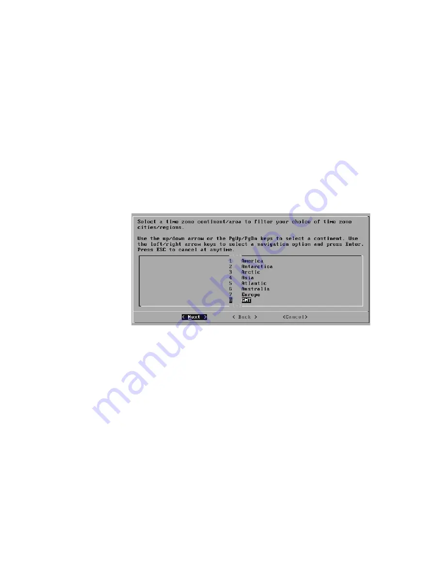
Figure 13  Time Zone Continent Window

Step 11

To select the time zone continent:

a    

Using the up or down arrow keys, or the PageUp or PageDown keys, select 

your time zone continent or area.

b    

Using the left or right arrow keys, select Next, then press Enter. The Time Zone 

Region window appears.

Summary of Contents for STRM 2500

Page 1: ...r Networks Inc 1194 North Mathilda Avenue Sunnyvale CA 94089 USA 408 745 2000 www juniper net Published 2013 03 15 Security Threat Response Manager STRM Series II Hardware Installation Guide Release 2...

Page 2: ...al generates and may radiate radio frequency energy If it is not installed in accordance with Juniper Networks installation instructions it may cause interference with radio and television reception T...

Page 3: ...STRM 500 II 14 Figure 9 Front Panel of STRM 500 II 15 Figure 10 STRM 500 II with the Flow Collector 4 port LAN card inserted 17 Figure 11 System Console Window 26 Figure 12 Set the Date and Time Windo...

Page 4: ...Figure 20 Front Rear Mounting flush to rack 33 Figure 21 Front Rear Mounting recessed in rack 34 Figure 22 Mid Mount in two post equipment rack 35...

Page 5: ...Table 7 STRM 2500 II Back Panel Components 9 Table 8 STRM 5000 II Front Panel LEDs 11 Table 9 STRM 5000 II Front Panel Ports 11 Table 10 STRM 5000 II Back Panel Components 12 Table 11 Required Ports o...

Page 6: ......

Page 7: ...anel Indicators and Features 10 Front Panel Indicators 10 Back Panel Features 12 3 INSTALLING AND CONNECTING THE STRM HARDWARE Additional Hardware Requirements 13 Installing the Hardware 14 LED Behavi...

Page 8: ...ON B RACK MOUNTING THE STRM SERIES II APPLIANCE Front Mounting Flush to Rack 35 Front Mounting Recessed in Rack 36 Front Rear Mounting Flush to Rack 37 Front Rear Mounting Recessed in Rack 38 Mid Moun...

Page 9: ...entions used in this guide Documentation Feedback We encourage you to provide feedback comments and suggestions so that we can improve the documentation You can send your comments to techpubs comments...

Page 10: ...with the following features Find CSC offerings http www juniper net customers support Search for known bugs http www2 juniper net kb Find product documentation http www juniper net techpubs Find solut...

Page 11: ...y products The STRM appliances use two drivers Security Information Management SIM and Security Event Management SEM for security analysis of external and internal threats SIM provides reporting and a...

Page 12: ...STRM Series II Hardware Installation Guide 4 STRM OVERVIEW...

Page 13: ...and Features STRM 5000 II Front Panel and Back Panel Indicators and Features STRM 500 II Front Panel and Back Panel Indicators and Features The STRM 500 II appliance has a 2U rack mountable chassis w...

Page 14: ...wer supply or temperature alarm has occurred LAN LEDs Left LED green Indicates that the link is active Momentary blinks for activity Right LED Indicates the link speed off 10 Mbps green 100 Mbps yello...

Page 15: ...STRM 500 II Back Panel Table 3 STRM 500 II Front Panel Ports Ports Description Console port One RJ 45 console port Network port Four RJ 45 Ethernet 10 100 1000 Table 4 STRM 500 II Rear View Components...

Page 16: ...as a 2U rack mountable chassis with optional redundant AC and DC power supplies 2U hot swappable dual redundant RAID10 array 8 GB of memory and a Gigabit Ethernet controller Front Panel Indicators See...

Page 17: ...er green Indicates that the appliance is powered on Hardware red Indicates that a fan power supply or temperature alarm has occurred LAN LEDs Left LED green Indicates that the link is active Right LED...

Page 18: ...ponents Description Cooling fans Draws air through vents of the chassis and exhaust it through vents on the other side of the chassis Power supply Provides power to all components OPEN OPEN OPEN OPEN...

Page 19: ...on Hardware red Indicates that a fan power supply or temperature alarm has occurred LAN LEDs Left LED green Indicates that the link is active Right LED Indicates the link speed off 10 Mbps green 100...

Page 20: ...0 describes the back panel features Figure 7 STRM 5000 II Back Panel Table 10 STRM 5000 II Back Panel Components Components Description Cooling fans Draws air through vents of the chassis and exhaust...

Page 21: ...t all STRM appliances or systems running STRM software storing data such as Consoles Event Processors or Flow Processors be equipped with an Uninterrupted Power Supply UPS We recommend that you instal...

Page 22: ...nel of STRM 500 II Step 3 Plug the other end of the power cord into a wall socket If your STRM appliance contains two power supplies plug each power cord into a separate power circuit to ensure that t...

Page 23: ...B 9 connector with 1 8 pinouts See Table 13 for RJ 45 chassis console connector pinout information Step 6 Push the power button on the front panel The green LED below the power button turns on The STR...

Page 24: ...ature alarm has occurred LAN LEDs Left LED green Indicates that the link is active Momentary blinks for activity Right LED Indicates the link speed off 10 Mbps green 100 Mbps yellow 1 Gbps Hard disk t...

Page 25: ...s ports that use the same protocol If the protocol does not support port based connections STRM combines all packets between the two hosts into a single flow record However a Flow Collector does not r...

Page 26: ...appliance includes the STRM software You control the appliance through a connected laptop or keyboard and monitor Follow the appropriate step Connect a laptop to the RJ 45 serial port on the front pan...

Page 27: ...ts that may exist in your deployment include Flow Processor The Flow Processor creates superflows aggregate flows before the flows reach the Classification Engine Classification Engine Analyzes flows...

Page 28: ...cess the event An offense is an event that has been processed through STRM using multiple inputs individual events and events combined with analyzed behavior and vulnerabilities The Magistrate priorit...

Page 29: ...condary DNS server Optional Public IP address for networks using Network Address Translation NAT E mail server NTP server Console only or Time server Identifying Security Monitoring Devices and Flow D...

Page 30: ...icates the message level you wish to log for example critical informational or debug No of Users indicates the maximum number of hosts and users using or being served by this device Network Location i...

Page 31: ...or information on defining servers within STRM If your network includes a large number of servers you can use CIDR or IP subnet addresses within the server networks category Table 16 Asset Identificat...

Page 32: ...STRM Series II Hardware Installation Guide 24 PREPARING YOUR SYSTEM FOR STRM SOFTWARE INSTALATION...

Page 33: ...op to connect to the system you must use a terminal program such as HyperTerminal Be sure to set Connect Using to the appropriate COM port of the serial connector and Bits per second to 9600 You must...

Page 34: ...arrow keys select one of the following tuning templates Enterprise Tunes properties for internal network activity University Tunes properties for education specific concerns ISP Tunes properties for I...

Page 35: ...b Using the left or right arrow keys select Next Press Enter c Go to Step 10 Step 10 To specify a time server a In the text field enter the time server name or IP address b Using the left or right arr...

Page 36: ...gion d Using the left or right arrow keys select Next Press the Enter key The Configure STRM window appears Figure 15 Configure STRM Window Step 12 To configure the STRM network settings enter values...

Page 37: ...field Step 13 Use the Tab key to move to the Next option Press Enter The New Root Password window appears Figure 16 New Root Password Window Step 14 To configure the STRM root password a Type a new p...

Page 38: ...word is the new root password you set during the installation process Step 3 Click Login To STRM STRM includes a default license key that allows you to access the interface for five weeks A window sho...

Page 39: ...0 is connected This happens with the STRM 5000 II LAN ports after a clean installation of STRM 2009 1 only Workaround Run the STRMswap tool for the Ethernet ports Note This method should only be used...

Page 40: ...isabling ethernet ports Old eth interface configuration files are Intel Corporation 82574L Gigabit Network Connection DEVICE eth0 BOOTPROTO dhcp DHCPCLASS HWADDR 00 E0 81 C2 7F 9B ONBOOT yes DHCP_HOST...

Page 41: ...juniper net Intel Corporation 82576 Gigabit Network Connection DEVICE eth1 HWADDR 00 E0 81 C2 7F DF ONBOOT no Intel Corporation 82574L Gigabit Network Connection DEVICE eth2 HWADDR 00 E0 81 C2 7F 9B O...

Page 42: ...STRM Series II Hardware Installation Guide 34 NEW OR CHANGED INFORMATION Step 9 Enter the following commad to reboot reboot...

Page 43: ...g Flush to Rack Front Rear Mounting Recessed in Rack Mid Mount in Two Post Equipment Rack Note If you are installing multiple STRM appliances in one rack you should install the lowest one first and pr...

Page 44: ...of the system forward as far as they will move See Figure 19 Step 3 Tighten the side rail screws Insert the two small screws in the recessed holes on the front rails and tighten Step 4 Insert 4 rack...

Page 45: ...r mount rail brackets into the backs of the front rails on either side of the chassis and align with your rear equipment rack posts Secure the rear mount rail brackets to your equipment rack with 2 ra...

Page 46: ...ils and tighten Step 4 Slide the rear mount rail brackets into the backs of the front rails on either side of the chassis and align with your rear equipment rack posts Secure the rear mount rail brack...

Page 47: ...the center on either side of the chassis Step 3 Attach the chassis to the equipment rack and insert the other two mid mount brackets on either side of the system to secure the chassis to the backs of...

Page 48: ...STRM Series II Hardware Installation Guide 40 RACK MOUNTING THE STRM SERIES II APPLIANCE...

Page 49: ...he disks fails Redundant array of independent disk RAID is an organization of multiple disks of fault tolerance and performance It is used in the servers for data storage and to replicate data among m...

Page 50: ...NG THE HARDWARE power load STRM Series II appliances also have a DC power supply option if you need DC power Cooling Fans The STRM 500 II and STRM 2500 II appliances have two cooling fans and the STRM...

Page 51: ...ax at 115VAC and 25C 80A Max at 240VAC and 25C 40A Max at 115VAC and 25C 80A Max at 240VAC and 25C 60 A for both AC and DC modules Fans 2x80 mm hot swap 2x80 mm hot swap 3 x 80mm hot swap Rack mountab...

Page 52: ...000 maximum 40000 maximum Compliance and safety Safety certification CAN CSA C22 2 No 60950 1 03 UL60950 1 2003 EN60950 1 2001 A11 IEC 60950 1 2001 CAN CSA C22 2 No 60950 1 03 UL60950 1 2003 EN60950 1...

Reviews: