
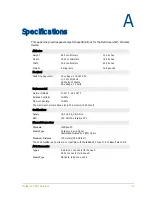
Appendix A Specifications
36
User’s Guide
C
ONSOLE
AND
M
ODEM
A
DAPTER
C
ONNECTIONS
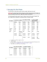
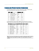
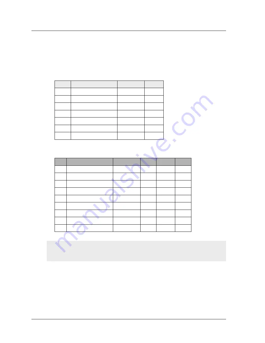
The following table lists the RJ-45 connector definitions. To employ a standard UART
port, both the console and the modem ports use this configuration.
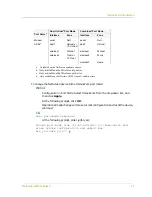
The table below lists the RJ-45 to DB-9 adapter connection definitions. To employ a
standard UART port, both the console and the modem ports must use this configuration.
RJ-45
Signal
Abbreviation DCE
1
Request To Send
RTS
In
2
Data Terminal Ready
DTR
In
3
Transmitted Data
TD
In
4, 5
Signal Ground
SGND
N/A
6
Received Data
RD
Out
7
Not Connected
8
Clear To Send
CTS
Out
DB9
Signal
Abbreviation DTE
DCE
RJ45
1
Data Carrier Detect
DCD
In
Out
NC
2
Received Data
RD
In
Out
3
3
Transmitted Data
TD
Out
In
6
4
Data Terminal Ready
DTR
Out
In
7
5
Signal Ground
SGND
N/A
N/A
4
6
Data Set Ready
DSR
In
Out
2
7
Request To Send
RTS
Out
In
8
8
Clear To Send
CTS
In
Out
1
9
Ring Indicator
RI
In
Out
NC
Note: If you use the Console cable that is provided with the NetScreen device to connect to
a modem, then you need to obtain and install a null modem adapter on the modem
connector.