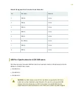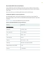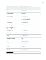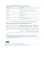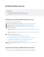
Table 33: Electrical Power Specifications of ACX500 GNSS Output Connector for Antenna Power
Output Current (mAmp)
(I-Load)
Output Voltage (V)
45 mAmp (maximum)
Vout = 3.3 V (+/-5%) – 22 ohm x I-Load
NOTE: ACX500 GNSS output current supports only 3 V antenna voltage, which work with
maximum current and supports voltage tolerance as calculated in
For antennas that do not have a voltage rating of 3 V DC, we recommend that you use an active
splitter or amplifier as required (DC block from ACX500 and antenna power from external power
source) that supports the antenna voltage.
ACX500 GNSS Antenna Surge Protection
For a roof antenna, we recommend that you provide additional surge protection in accordance to the
regulations and standards for lightning protection in the country where the ACX500 router is installed.
NOTE: We recommend that you use an external first-level fast lightning protector that has
clamping voltages of 15 V and 20 V.
WARNING: Make sure that grounding is available and that it meets local and national
electrical codes. For additional lightning protection, use lightning rods, lightning
arrestors, or surge suppressors.
Antenna Installation Verification
After installing the GNSS antenna, verify that the installation is properly done:
• Verify that all the cables and connectors are installed correctly and securely fastened. Ensure that all
connectors have been protected from weather by using the latest RF cabling installation and
protection guidelines.
• Verify that the GNSS antenna interface status is good in the respective GPS monitoring application.
Also, verify the status of the GPS 1PPS LED on the ACX500 router.
117


