


JUNCTEK
JDS8000 Series User’s Manual
Inspection
When you get a new JDS8000 series arbitrary function signal generator, it is
recommended that you inspect the instrument according to the following steps.
Inspect the Packaging
If the packaging has been damaged, do not dispose the damaged packaging
or cushioning materials until the shipment has been checked for completeness
and has passed both electrical and mechanical tests. The consigner or carrier
shall be liable for the damage to the instrument resulting from shipment. We
would not be responsible for free maintenance/rework or replacement of the
instrument.
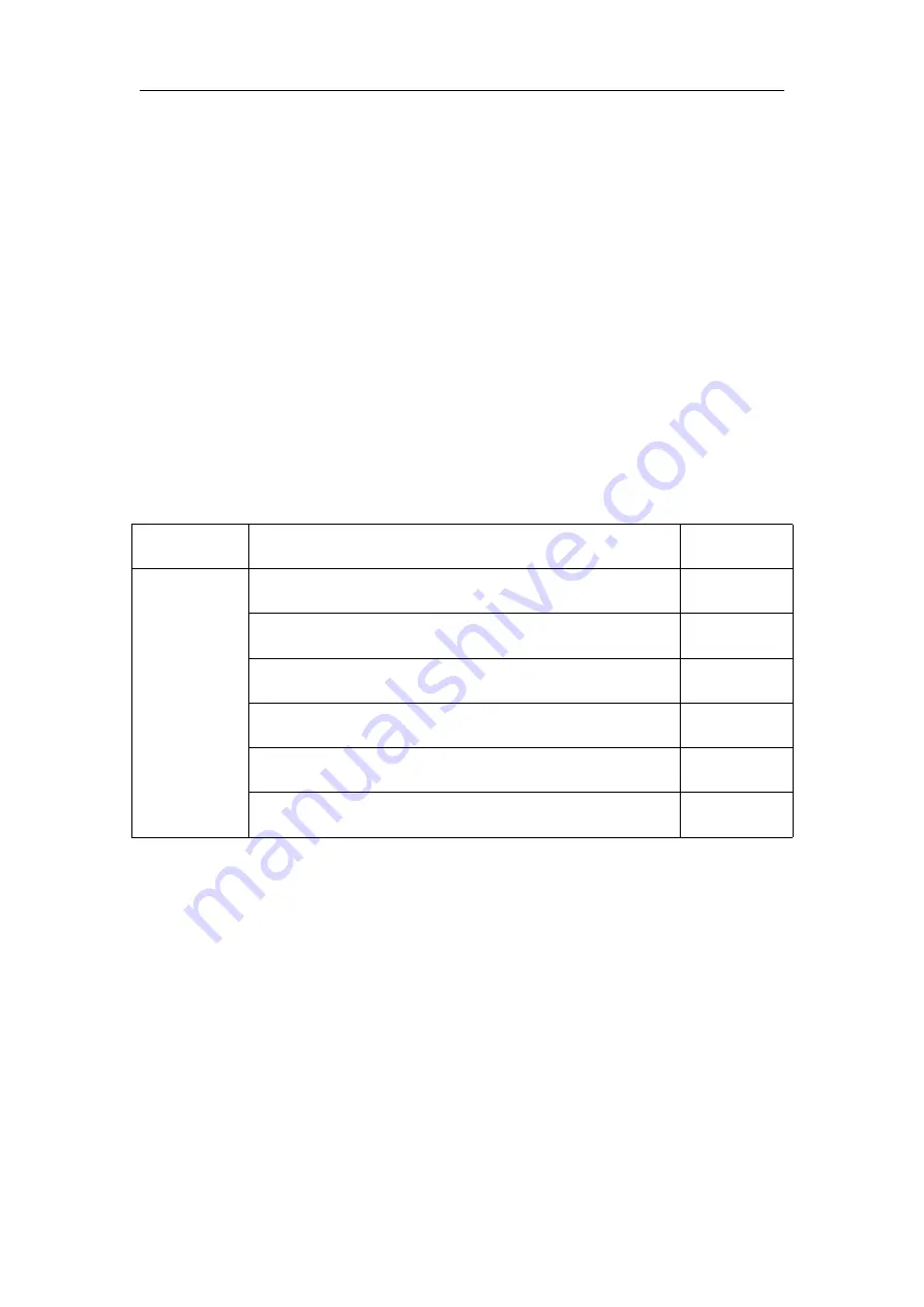
Check the Contents
Please check the contents according to the packing lists. If the instruments are
damaged or incomplete, please contact your JUNCTEK sales representative.
Host
JDS8000 arbitrary function signal generator
1pc
Accessory
Power cord
1pc
USB cable
1pc
BNC to alligator clips test lead
2pc
BNC male plug test lead
1pc
Certificate of conformity
1pc
Quick guide
1pc
Inspect the Instrument
In case of any mechanical damage, missing parts, or failure in passing the
electrical and mechanical tests, contact your JUNCTEK sales representative.
Summary of Contents for JDS8000 Series
Page 1: ......