4 Electrical connection
26
4.4
Connection diagram
4.4.1
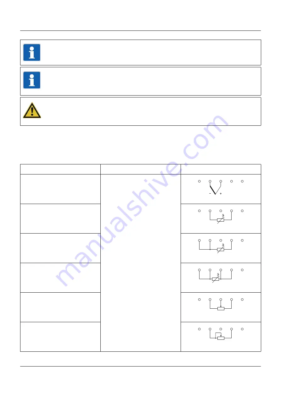
Analog inputs 1 to 6 (options 1 and 2)
NOTE!
The front-side USB host interface is intended exclusively for connecting a USB flash drive.
Any other use is not admissable.
NOTE!
The quality of the USB cable and the USB flash drive has an influence on the correct function
of the device. It is recommended to use the components provided by the manufacturer (ac-
cessories).
CAUTION!
The device is not suitable for connecting to a PoE (Power over Ethernet) port.
There is a risk of damage to the device.
Connect the device to an Ethernet port without PoE.
Measuring probe
Connection element / Assignment Terminals and connection symbol
Thermocouple
7. / Analog input 1
8. / Analog input 2
9. / Analog input 3
11. / Analog input 4
12. / Analog input 5
13. / Analog input 6
RTD temperature probe
two-wire circuit
RTD temperature probe
three-wire circuit
RTD temperature probe
four-wire circuit
Resistance transmitter
Resistance/potentiometer
two-wire circuit
1
2
3
4
5
1
2
3
4
5
1
2
3
4
5
1
2
3
4
5
1
2
3
4
5
E
S
A
1
2
3
4
5


