


6 Safety-related applications
28
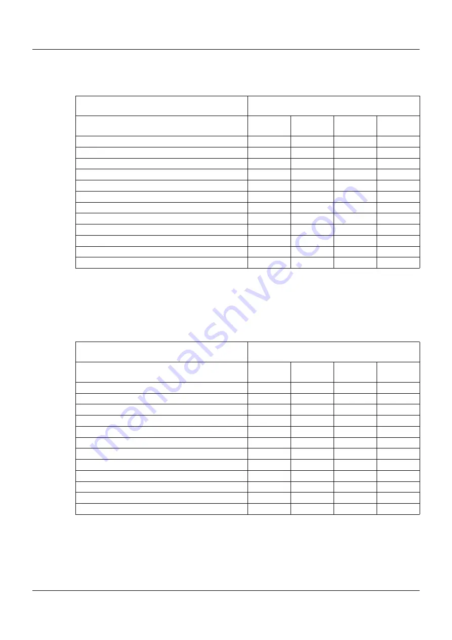
6.15
Excerpt from FMEDA report
Normally open configurations C1-C4
Normally closed configurations C5-C8
Failure category
IEC 61508:2010
Failure rates (in FIT)
C1
Normal
C2
Normal
C3
Inverted
C4
Inverted
Safe detected (
λ
SD
)
0
0
0
0
Safe undetected (
λ
SU
)
187
252
189
254
Dangerous detected (
λ
DD
)
6
6
6
6
Dangerous undetected (
λ
DU
)
48
83
51
86
No effect
104
104
106
106
Total failure rate (safety function)
241
341
246
346
SFF
a
a
The complete subsystem will need to be evaluated to determine the overall safe failure fraction. The
number listed is for reference only.
80 %
75 %
79 %
75 %
DC
9 %
7 %
9 %
6 %
SIL AC
b
b
SIL AC (architectural constraints) means that the calculated values are within the range for hardware
architectural constraints for the corresponding SIL but does not imply all related IEC 61508 require-
ments are fulfilled. In addition it must be shown that the device has a suitable systematic capability for
the required SIL and that the entire safety function can fulfill the required PFD / PFH values.
SIL 2
SIL 2
SIL 2
SIL 2
Failure category
IEC 61508:2010
Failure rates (in FIT)
C5
Normal
C6
Normal
C7
Inverted
C8
Inverted
Safe detected (
λ
SD
)
0
0
0
0
Safe undetected (
λ
SU
)
177
232
179
234
Dangerous detected (
λ
DD
)
6
6
6
6
Dangerous undetected (
λ
DU
)
58
103
61
106
No effect
104
104
106
106
Total failure rate (safety function)
241
341
246
346
SFF
a
a
The complete subsystem will need to be evaluated to determine the overall safe failure fraction. The
number listed is for reference only.
75 %
69 %
75 %
69 %
DC
9 %
5 %
8 %
5 %
SIL AC
b
b
SIL AC (architectural constraints) means that the calculated values are within the range for hardware
architectural constraints for the corresponding SIL but does not imply all related IEC 61508 require-
ments are fulfilled. In addition it must be shown that the device has a suitable systematic capability for
the required SIL and that the entire safety function can fulfill the required PFD / PFH values.
SIL 2
SIL 2
SIL 2
SIL 2
Summary of Contents for Ex-i
Page 2: ......
Page 10: ...2 Safety requirements and installation instructions 10...
Page 18: ...4 Configuration 18...
Page 20: ...5 Comparison of the safety data 20...
Page 30: ...6 Safety related applications 30...
Page 31: ......


