– 125 –
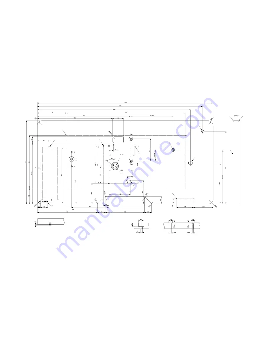
13. Table drawings
(1) Table type for longitudinal Installation
Z-Z
Y-Y
1
2
5
4
6
7
9
!0
!1
!2
!3
!4
!3
3
8
1
4- drilled hole 2, 10 deep on the rear side (Stand installing hole)
8
Drilled hole 8
2
Drawer stopper installing position One place on the rear side
9
Drilled hole 9, 20 spot face 17 deep
3
JUKI logotype
!0
2- drilled hole 2, 10 deep on the rear side (Power switch installing hole)
4
4- drilled hole 8
!1
Drilled hole 17
5
Drilled hole 30, 51 spot face 16 deep
!2
Drilled hole 28
6
Oil drain funnel installing hole
!3
R2 (all corners)
7
3- drilled hole 7, 6 deep
!4
Right side
For LK-1900AN
For LK-1901AN
For LK-1903AN
Part No.: 40006886
Summary of Contents for LK-1900AN
Page 30: ... 18 11 Hook adjustment Standard adjustment For DP 17 For DP 5 0 05 to 0 1 mm ...
Page 100: ... 88 8 Needle thread clamp mechanism area Grease Grease Grease Grease Grease ...
Page 101: ... 89 9 LK 1901AN relations Grease Grease Grease Grease Grease Grease Grease Grease ...
Page 102: ... 90 10 LK 1903AN relations Grease Grease Grease ...
Page 129: ... 117 12 Circuit diagrams 1 Block diagram A ...
Page 130: ... 118 2 Power supply circuit diagram A ...
Page 131: ... 119 3 Power supply circuit diagram B ...
Page 132: ... 120 4 Power supply circuit diagram C ...
Page 133: ... 121 5 Servo motor circuit diagram ...
Page 135: ... 123 7 MAIN PANEL board circuit diagram ...
Page 139: ......


