


4
Power
Adapter
Plug
Charger
Jack
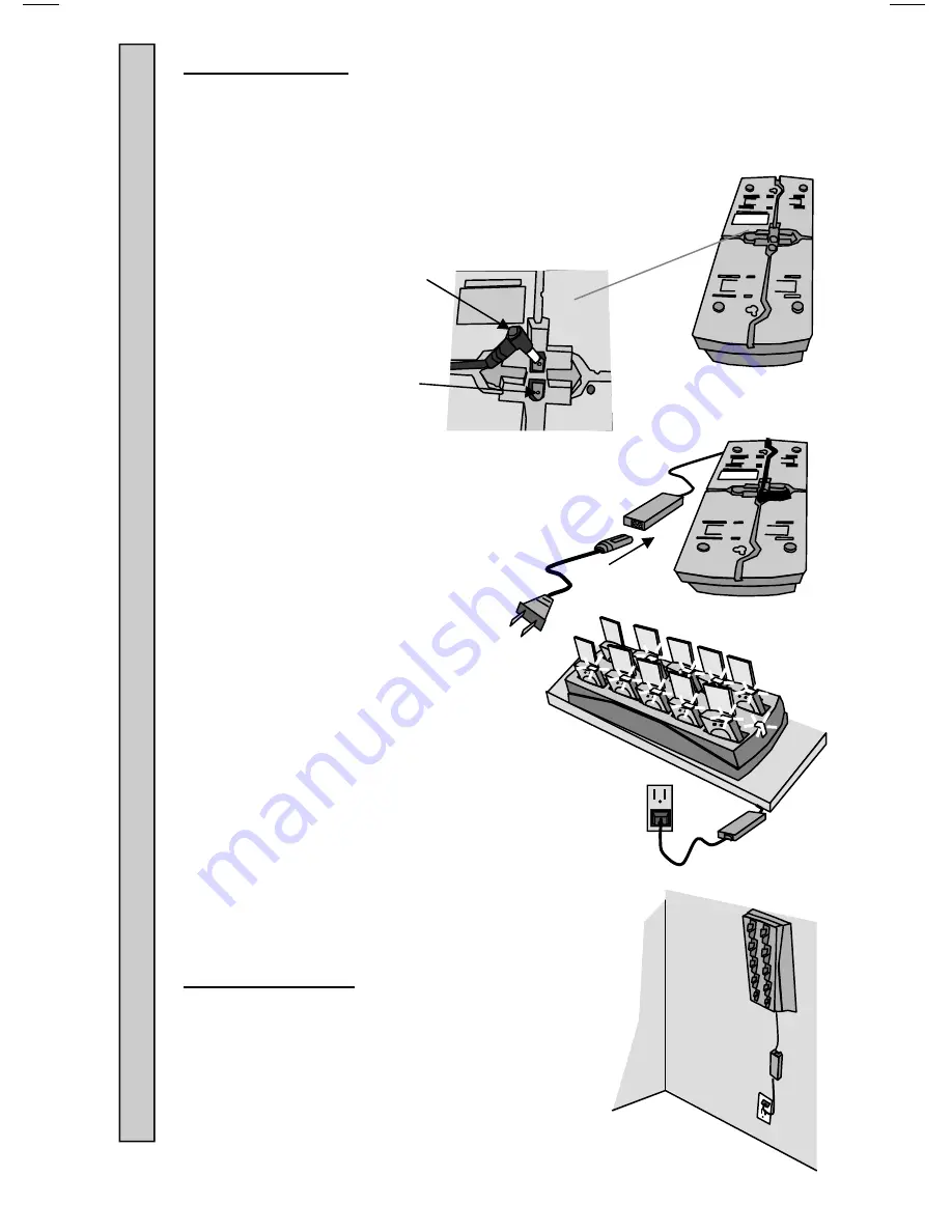
Connecting Power:
1. Insert
the
Power Adapter
plug into jack on the bottom of
the
Charger
.
2. Feed the wires through the guides in the bottom of the
Charger
.
3. Connect
the
Power Adapter
to the
AC
Power Cord
.
4. Plug
the
AC Power Cord
into a
110-240VAC outlet.
5. The green LED on the
Charger
will light
(ON).
6. Once
the
Charger
is powered (ON), the
Pagers
can be inserted.
Mounting Chargers:
Chargers
can be wall, shelf or counter top
mounted.
Mounting hardware is user supplied.
M
o
unting Chargers
Connecting Power to
Chargers


