JTECH QuikCall 321045B5 Manual Download Page 3

 3 


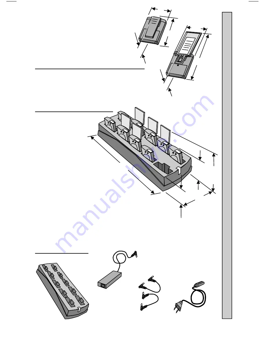
Pager (With Spring Clip): 



LxWxH 1.4x 2.2x 3.8” (35x56x97mm) 



Weight  2.6oz (74gm) 


Pager (With Promotional Paddle And Inserts): 



LxWxH 1.2x 2.2x 7.7” (31x56x196mm) 



Weight  4.4oz. (124gm) 


Charger Dimensions and Weight  


Charger Only 



LxWxH 13.5x 4.8x 
2.6” (343x122x65mm) 



Weight  1.64lbs  (0.75kg) 


Charger and 10 Pagers With Clips: 



LxWxH1 13.5x 4.8x 4” (343x122x102mm) 



Weight 3.41lbs (1.55kg) 


Charger and 10 Pagers With Promotional Paddles: 



LxWxH2 13.5x 4.8x 8.8” (343x122x224mm) 



Weight 4.38lbs (1.99kg) 


Charger Components: 


2.4 A Power 
Adapter 

Jumper Wires 

(Optional Equipment) 

AC Power 
Cord 

JTECH 

10 Position 

Charger 

H1 

H2 


            Charger Comp

onents        


D

efin

e what 

tran

s

m

itter is to b

e used. No

te

:  

Summary of Contents for QuikCall 321045B5

Page 1: ...Pager and Charger Guide Part Number 321045B5 Premises Pager System QuikCall Pagers...

Page 2: ...SS 210 statement This device complies with Industry Canada licence exempt RSS standard s Operation is subject to the following two conditions 1 this device may not cause interference and 2 this device...

Page 3: ...6 343x122x65mm Weight 1 64lbs 0 75kg Charger and 10 Pagers With Clips LxWxH1 13 5x 4 8x 4 343x122x102mm Weight 3 41lbs 1 55kg Charger and 10 Pagers With Promotional Paddles LxWxH2 13 5x 4 8x 8 8 343x...

Page 4: ...m of the Charger 3 Connect the Power Adapter to the AC Power Cord 4 Plug the AC Power Cord into a 110 240VAC outlet 5 The green LED on the Charger will light ON 6 Once the Charger is powered ON the Pa...

Page 5: ...both Chargers together 3 Insert the Power Adapter plug into jack on the bottom of the Charger 4 Use the Jumper Wire optional to connect both Chargers together 5 Feed the wires through the guides in th...

Page 6: ...fully charge within three hours 5 If not returned within 24 hours charging time of up to 8 hours may be required to fully charge batteries 6 When not in the Charger each Pager continues to indicate b...

Page 7: ...h confirming the it is ready to receive a page 4 Enter the number of the Pager on the Controller 5 Press or SEND button to send the page 6 The XMIT light on the Controller will turn ON confirming the...

Page 8: ...3 seconds and turn off 7 The Pager will receive a single one second vibration factory setting 8 The light on the panel next to that Pager number will continue to stay ON for 40 seconds factory setting...

Page 9: ...has been assigned to the TELCO Module installed 6 Listen for a voice message from the telephone that confirms the Controller is ready 7 Within 8 10 seconds using the telephone keypad enter the Pager n...

Page 10: ...Pager over 2 Push or pull the small plastic tab as shown in below and slide the Clip or Paddle off 3 Slide the new Clip or Paddle on until a click can be heard locking the clip or paddle onto place M...

Page 11: ...y the user 2 If using a Spring Clip it must be removed to access the battery door screw 3 Use a 1 Philips screwdriver to remove the screw 4 Slide the battery door and Pager Clip off 5 Carefully slip a...

Page 12: ...isplayed on the interior and exterior of the package s This warranty does not apply to equipment which has been damaged by accident negligence or misapplication or has been altered or modified in any...

Reviews: