www.modellmarkt24.ch
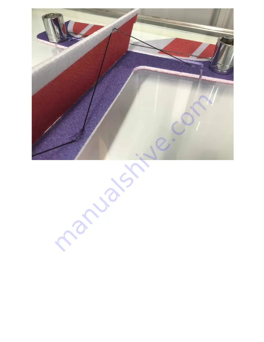
Shown above is the bottom fuse bracing for the rear of the fuselage. Lengths
found in diagram.
Page 1: ...www modellmarkt24 ch JTA Innovations 33 MXS www modellmarkt24 ch...
Page 2: ...ing of the model If ope ating in the United States please make su e that you ha e membe ship ith the Academy of Model Ae onautics and follo AMA ules Please ope ate the model at AMA flying sites If li...
Page 3: ...A Hobbyknife with blades Scissors Heat gun or lighter for heat shrink Assorted phillips and flat blade screwdrivers Assortment of small drill bits Drill Needle nose pliers Driver set 90 degree square...
Page 4: ...schemes are designed by Kim Quenette and are sure to catch attention JTA Innovations also introduces another development in the carbon fiber construction technique with this release The use of flat ca...
Page 5: ...www modellmarkt24 ch Carbon fiber layout Aileron linkages 70mm long each Elevator and rudder linkages 400mm long each www modellmarkt24 ch...
Page 6: ...www modellmarkt24 ch www modellmarkt24 ch...
Page 7: ...the aileron bracing is done using flat carbon fiber glued into the slots creating durability for the aileron Please see the carbon fiber diagram for your airframe to determine which size carbon strips...
Page 8: ...www modellmarkt24 ch Wing bracing shown above The center wing spar is the supplied carbon fiber square stock Cowl glued to the fuselage www modellmarkt24 ch...
Page 9: ...h The horizontal piece of the fuselage also uses flat carbon fiber spanning the entire length from the rear wing spar to the horizontal stab spar Elevator flat spar and h stab flat spar shown above ww...
Page 10: ...dellmarkt24 ch Now that rigidity is established it is very important to break in the hinges by flexing them all the way over and weighing them down Let them rest for at least 60 minutes www modellmark...
Page 11: ...www modellmarkt24 ch You can now prepare the bottom half of the fuselage Test fit this into each slot as shown above before glueing www modellmarkt24 ch...
Page 12: ...www modellmarkt24 ch If deciding to place glue on the horizontal part of the fuselage you can mark out where the glue will be placed as shown above after test fitting the fuselage www modellmarkt24 ch...
Page 13: ...www modellmarkt24 ch Using the marks that you just made place your glue along the fuselage www modellmarkt24 ch...
Page 14: ...extremely important to make sure that the bottom vertical part of the fuselage stays 90 degrees to the horizontal fuselage while the glue is setting This can have a huge effect on the flying character...
Page 15: ...Some airframes may have a larger gusset or joiner that overlaps the leading edge You will also find dots towards the tip of each wing to determine where to glue the carbon rods The same goes for the...
Page 16: ...www modellmarkt24 ch Shown above is the wing bracing glued into the bottom part of the fuselage www modellmarkt24 ch...
Page 17: ...24 ch Just like the aileron bracing it is very important to use weight towards the wing tip while the carbon wing bracing is setting to keep the leading edge of the wing as straight as possible www mo...
Page 18: ...Shown above is one of the carbon fiber landing gear legs that come pre glued to the axle The larger of the two EPP foam circular collars will slide on first No need to apply glue to anything quite yet...
Page 19: ...www modellmarkt24 ch Next with no glue needed slide one of the wheels on to the axle all the way up to the first foam collar Make sure it is spinning freely www modellmarkt24 ch...
Page 20: ...ch Now locate the plywood carbon fiber laminated collar to slide up next to the plastic wheel Once again do not apply glue yet as the tire will need to spin as freely as possible around the axle www...
Page 21: ...www modellmarkt24 ch Locate the smaller of the two circular foam collars to slide onto the axle next www modellmarkt24 ch...
Page 22: ...the wheel pants You can place a bit of adhesive on the last foam collar before sliding the wheel pant on to the axle If desired you can place some adhesive on the outside of the wheel pant where the c...
Page 23: ...in the side of the bottom of the fuselage to slide each landing gear leg into Make sure that the bottom of each leg is placed to where the airplane will sit level on the ground Also shown is the first...
Page 24: ...llmarkt24 ch Locate the EPP landing gear cover that will be placed over the carbon fiber landing gear leg Test fit this piece then glue it on over the carbon fiber using the pre cut slot www modellmar...
Page 25: ...www modellmarkt24 ch Shown above is the bottom fuse bracing for the rear of the fuselage Lengths found in diagram www modellmarkt24 ch...
Page 26: ...ch Shown above is the rest of the bottom fuselage bracing up to the wing bracing You should be able to notice the dots marked to help guide where each rod will be placed Lengths found in diagram www...
Page 27: ...www modellmarkt24 ch Above is other side of the fuselage carbon fiber arrangement www modellmarkt24 ch...
Page 28: ...www modellmarkt24 ch Locate the short flat carbon fiber piece that will be used as the tail piece for taxiing taking off and landing www modellmarkt24 ch...
Page 29: ...modellmarkt24 ch Glue the tailpiece into place as shown above while making sure that it is on the same angle of the bottom of the fuselage to ensure that the airframe will sit level www modellmarkt24...
Page 30: ...ervo Using the extension will provide the maximum amount of aileron throw To join the two arms use carbon fiber rods as shown above and glue them in through the holes lined up on each arm It is import...
Page 31: ...d of the servo arm and then fasten the bottom plastic piece through the pin You may want to put a bit of CA on the bottom of the pin and plastic piece to provide the most possible strength The mini EZ...
Page 32: ...servo by plugging it into your receiver and powering it on with zero sub trim and trim you can glue it into the servo slot that is the most forward on the airframe with the output shaft facing rear T...
Page 33: ...n the side of the fuselage The arms used for the elevator and rudder servos are the singles For both the elevator and rudder servos face the output shaft towards the rear For the MXS position the serv...
Page 34: ...www modellmarkt24 ch Shown above is the rudder servo mounted www modellmarkt24 ch...
Page 35: ...e Two long ones will be used for the ailerons and one long horn for the rudder The shorter one will be used on the elevator You will notice a cutout on the bottom of the elevator horn that will fit ov...
Page 36: ...s shown above Use regular CA to glue these two together The straight metal piece will be what slides into the mini EZ connector on the servo arm of the aileron The metal Z bend provided in the kit wil...
Page 37: ...4 ch Shown above is the entire aileron linkage assembly for one aileron Notice the heat shrink over each glued end as well as the straight end clamped into the mini EZ connector on the servo arm www m...
Page 38: ...inkage and the heatshrink is cut and slid on before the Z bend is glued The rudder linkage will be done the same way later on You will be able to tell where the guides will need to be glued in based o...
Page 39: ...www modellmarkt24 ch Above is the finished elevator linkage setup with the guides glued into the fuselage and the elevator centered and clamped into the mini EZ connector www modellmarkt24 ch...
Page 40: ...he bottom of the fuse to glue the top of the fuselage into place Once again it is important to keep this as straight as possible Now that the top of the fuselage is glued in you can glue the other rea...
Page 41: ...of the bottom vertical fuselage Make sure they are glued in a location that allows for full down elevator throw Shown above is the carbon rod that will go on each side of the fuselage It will be used...
Page 42: ...e setting You can now locate the final long control horn and glue it into the slot on the side of the rudder This will be used for the rudder linkage that will be constructed in the same way as the on...
Page 43: ...t of the fuselage by bending the attached tabs 90 degrees and sliding it on without glue Once test fitted place adhesive on the inside of the motor mount covering every spot then place again on the fr...
Page 44: ...the electronic speed controller on the other side of the fuselage The two cutouts on the top and bottom of the plate is where the provided velcro strap will slide through Shown above is the ESC mounte...
Page 45: ...quipment used and personal flying preferences The long piece of velcro mounted above is the location of the battery for this setup To save space on the other side of the fuselage the battery connector...
Page 46: ...ounted to the provided motor mount If desired locate the side force generators that will be glued into the counterbalances of the ailerons Some airframes may require the SFGs to be glued into differen...
Page 47: ...www modellmarkt24 ch Shown above are the pieces included for the stand assembly Here is the stand fully assembled www modellmarkt24 ch...
Page 48: ...d people in this hobby and I am using this business to contribute my part to the cause of model aviation We hope that this purchase is a success for you and that it brings the type of joy to you that...