4. Operation 35
◎
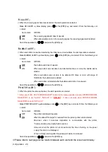
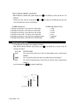
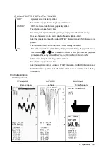
When PRINTER PORT OUT is “PC"
COPY
:
Data cannot be output.
When the print or the data output is operated, it becomes an error.
HISTORY
:
Memorized all data and maintenance system information are output.
LOG
:
This data output is available only the history display
mode. Data and maintenance system information in
the same time as the case of above-mentioned
“PRINTER" LOG are output.
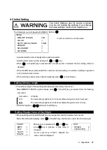
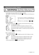
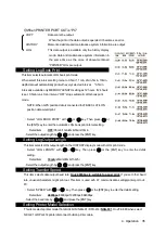
Setting Log Book Print
This item selects automatic LOG book print mode.
When select this interval setting menu to 0.5min*, 1min, 2min, 5min, 10min,
depth data will automatically print with every selected interval. * 0.5min
interval is available only MEMORY LENGTH setting as 12 hours. If 24 hours
is set, 0.5min runs 1min interval. “OFF” stops automatic LOG book print
mode.
NOTE: When GPS position data is connected to JFE-680, LAT/LON
position data would print.
・
Select “LOG BOOK PRINT” with or key. Then press or
the [ENT] key to enter the automatic LOG book print interval setting.
Detail item
:
OFF
/0.5min/1min/2min/5min/10min
・
Select the output length by and press the [ENT] key.
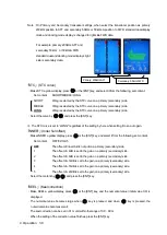
Setting Log Output Length
This item selects LOG output length on the HISTORY display mode with LOG print mode.
・
Select “LOG LENGTH” with or key. Then press or the [ENT] key to enter the detail
setting.
Detail item
:
10min
/20min/30min/1hr/2hr
・
Select the output length by and press the [ENT] key.
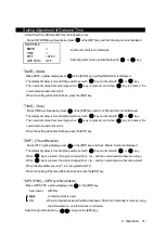
Setting Transfer Speed
This item selects data output baud rate.
Only 4800bps is suitable to paper print.
If you set other baud
rate, unusual characters might print out. This item is used with 4.7 communication setting/printer port out :
PC.
・
Select “SPEED” with or key. Then press or the [ENT] key to enter the detail setting.
Detail item
:
4800bps
/9600bps/19200bps/38400bps
・
Select the baud rate by and press the [ENT] key.
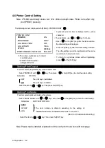
Setting Printer Model Selection
This item selects printer model from BUILD-IN/ NKG-91/ DPU-414/
NKG-901
. On JFE-680 when select
NKG-91 or DPU-414 printer disconnect build-in printer cable.
Summary of Contents for JFE-680 -
Page 2: ......
Page 9: ...External View External View vii NO ALERT ...
Page 18: ...1 5 System Configuration 1 Introduction 6 alert alert alert alert alert alert alert ...
Page 54: ...5 1 Installing the Recorder Unit Flush Mount Equipment Figure 3 1 5 Installation 42 Unit mm ...
Page 55: ...Wall Mount Equipment Figure 3 2 5 Installation 43 Unit mm ...
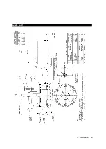
Page 57: ...NKF 345 5 Installation 45 ...
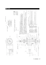
Page 58: ...NKF 392C 5 Installation 46 ...
Page 59: ...NKF 393 5 Installation 47 ...
Page 60: ...NKF 394 5 Installation 48 ...
Page 61: ...NKF 396 5 Installation 49 ...
Page 84: ......
Page 85: ......


