background image

Operation

21

<


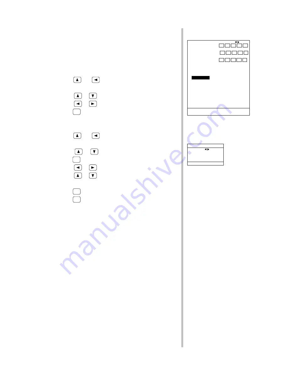
Varying the VRM EXPAND Mode Range (VRM EXP. RANGE)

The VRM EXPAND mode range is selectable from five preset choices.

These five presets may be varied as desired (in range of 1 to 100).

To vary the VRM EXPAND mode range, follow these steps:

l

 Choosing from among five VRM EXPAND mode ranges

1.


Press the 

 and 

 keys at the same time to call up the main

menu.

2.


Using the 

 or 

 key, move to “4.VRM EXP. RANGE.”

3.


Using the 

 or 

 key, move to the range to choose.

4.


Press the 

GRAPH

 key to return to the fishfinding display.

l

 Varying a preset VRM EXPAND mode range

1.


Press the 

 and 

 keys at the same time to call up the main

menu.

2.


Using the 

 or 

 key, move to “4.VRM EXP. RANGE” and

press the 

MARK

 key.

3.


Using the 

 or 

 key, move to the range to vary.

4.


Using the 

 or 

 key, increase or decrease the range value.

5.


Repeat steps 

3

 and 

4

 to vary other ranges as needed.

6.


Press the 

MARK

 key to return to the main menu.

7.


Press the 

GRAPH

 key to return to the fishfinding display.


   1.PRESET STD RANGE ≫   1   2   3   4   5 
                            10   20   30   40   50


      6   7   8   9  10

                     RANGE  60   80  100  150  200
                          11 12 13 14 15


  250  300  400  500  800

                     STEP


10                    

▲ 2.BTM EXP.RANGE   ≫     2    3    4    5   10
▼ 3.B.DISCRIM RANGE ≫    10   20   30   40   50
   

4.VRM EXP.RANGE

   ≫     5   10   15   20   50

   5.STD RANGE MODE    PRESET  STEP  AUTO
   6.BACK COLOR        NORMAL  1   2   3
   7.COLOR MODE        NORMAL  1   2   3
   8.USER COLOR      ≫
   9.DISPLAY         ≫
  10.SET GRAPH       ≫  DEPTH/  DEPTH/


   TEMP   BH

  11.UNIT            ≫
GRAPH


:


RETURN TO F/F

MARK


:


GOTO SUB MENU

Main Menu

4.VRM EXP.RANGE

        VRM EXP.RANGE


     A   B   C   D   E
 ▲   5   10   15   20   50 
 ▼
 MARK


:


RETURN TO MENU

VRM EXP.RANGE

Summary of Contents for JFC-130 -

Page 1: ...COLOR ECHO SOUNDER INSTRUCTION MANUAL ...

Page 2: ......

Page 3: ...truction manual carefully for future reference is highly recommended In the event that you have an operational problem or malfunction this manual will provide useful instructions Please write down the type of the connected transducer the following first It is necessary for maintaining this unit Frequency Transducer High frequency kHz CFT Low frequency kHz CFT Thank you for purchasing our JRC JFC 1...

Page 4: ...operated correctly This indication is shown where any person is supposed to be injured if this indication is neglected and these equipment are not operated correctly Examples of pictorial indication The ê mark represents CAUTION including DANGER and WARNING Detailed contents of CAUTION Electric Shock in the example on the left is shown in the mark The x mark represents prohibition Detailed content...

Page 5: ...failure may occur Do not place a vessel containing water etc or a metallic object on this set When water spills or when water or the object enters the set a fire an electrical shock or a failure may occur Do not insert or remove the power cord or operate switches with a wet hand Otherwise you may suffer from an electrical shock Do not supply the power from this equipment or the NBA 3263 rectifier ...

Page 6: ... turn off the main unit unplug the power supply terminal and contact our company branch or local office Continuing operation as is may cause a fire electric shock or malfunction In the event that smoking or burning odors are detected immediately terminate operation of the set and contact your dealer Continuing operation as is may cause a fire or electrical shock Never attempt to service the interi...

Page 7: ... the temperature rises above 50 Otherwise a malfunction or defect may occur Do not place the set in an unstable position such as on a shaking stand or tilting place Otherwise this set may drop or turn over resulting in an injury Do not bring the set in a cooled state abruptly into a warm room A high voltage may leak due to dew condensation resulting a failure In this case use the set after leaving...

Page 8: ...aged resulting in a fire or an electrical shock Do not install the units on the place being poor ventilation Otherwise the set that is heated may cause a fire or failure When the set is unused for a long period be sure to turn off the power switch of the set and then remove the power code to assure safety When turning on the power be sure not to press any operator panel key at the same time Altern...

Page 9: ...e of SSB radio the distance should be increased 2 m 7ft More than 2 m 7ft from the path of a radar beam A radar beam can normally assume to spread 20 degrees above and below the radiating element The equipment should be supplied from a different battery than the one used for engine start Voltage drops below 10 8V in the power supply to our products can cause the equipment to reset This will not da...

Page 10: ... to your nearest JRC dealer We will use any such information to improve our quality standards Safety Some products generate high voltages and so never handle the cables connectors when power is being supplied to the equipment Suppression Ferrites The following illustration shows the range of suppression ferrites fitted to JRC equipment If your JRC equipment is going to be connected to other equipm...

Page 11: ...s to itself using the frequency selector A long transmission pulse may impair the range resolution of the image In the case of a echo sounder with a pulse selector be sure to use it by selecting a shortest possible pulse A wide angle of directivity of the oscillator may cause the set to catch noises locate the fish erroneously or decrease the power of the ultrasonic wave to be emitted in the requi...

Page 12: ...Outside View x Outside View Outside View of the JFC 130 130HP Vertical mount Outside View of the JFC 130 130HP Horizontal mount ...

Page 13: ...Terms xvi SECTION 1 Introduction 1 1 1 Function 1 1 2 Features 2 1 3 Components 3 1 4 Structure 4 1 5 Power and Transducer Connection 5 SECTION 2 Names and Functions of Components 6 Keyboard unit keys 8 Keyboard unit keys and functions 9 SECTION 3 Operation 10 3 1 Screen layout 10 Fishfinding Displays 10 STANDARD mode 10 VRM EXPAND mode 10 BOTTOM LOCK EXPAND mode 11 Bottom discrimination mode 11 ...

Page 14: ...nding Menu MARK key 16 Exiting the Fishfinding Menu to a fishfinding display GRAPH key 16 Call up and Exiting the STC ADJUST Menu MARK GRAPH key 16 Resetting to Prerecorded Settings CUSTOM key 17 Recording Settings CUSTOM key 17 Key lock function MARK DAY NIGHT key 18 3 3 Function Key Operations 19 Range Operations 19 Changing a Range RANGE RANGE key 19 Varying a Range PRESET STD RANGE 19 Varying ...

Page 15: ...e of A Scope Display A SCP MODE 31 Color Operations 32 Changing the Background Color BACK COLOR 32 Changing the Fishfinding Display Colors COLOR MODE 32 Customizing Colors to be Used USER COLOR 33 Graph Operations SET GRAPH 34 Changing the Display Time 34 Changing the Water Temperature Range 34 Changing the Depth Range 35 To display the hardness of the sea bottom BH value on a graph DEPTH BH 35 Un...

Page 16: ... 45 Error Messages 46 CAN T BACK UP 46 CAN T READ DATA 46 LANGUAGE TYPE 46 Executing a Master Reset 47 3 4 Remote Controller Functions 48 What You Can Do with the Remote Controller 48 Connecting the Remote Controller 48 Remote Controller Buttons and Functions 48 3 5 Remote Controller Operation 50 Record Replay Function 50 Recording an Image 50 Replaying a Recorded Image 51 Alarm Function 52 Enabli...

Page 17: ...Contents xv SECTION 7 Disposal 59 SECTION 8 Index 60 SECTION 9 Specifications 62 ...

Page 18: ...p water and less sensitivity for shallow water Hull The exterior surface of a ship Keel The center of the hull running from the bow to the stern Port Left nautical term Range The depth scale which you can set to either automatic or manual The range value appears at the bottom right of your display Starboard Right nautical term Stern The rear of a vessel nautical term Transducer A device mounted on...

Page 19: ... of the low frequency display high frequency display and parallel display of low and high frequency images as well as such functions as the partially enlarged display mode sea bottom enlarged display mode and mixed display mode Further the function of parallel display of A scopes where the intensity of the response from the fish is displayed in both color tone and width is provided In addition the...

Page 20: ...er narrows oscillation lines to clearly monitor small fish schools near the sea surface through high speed transmissions at a rate of up to 600 JFC 130 300 JFC 130HP cycles per minute The BOTTOM LOCK EXPAND mode with 16 halftone colors precisely discriminates between the sea bottom and bottom fish schools n More Numerous Features Simultaneous drawing When the screen display mode is changed the pic...

Page 21: ...unit NCM 774 Transducer Depends on the frequency and mounting method 1 or 2 JFC 130HP Description Model No Qty Remarks packing Display unit NWZ 146 1 Video cable CFQ 6901 1 5 m with connectors Power cable CFQ 6900 1 5 m with connectors Tapping screws BRTG07127 4 M6 2 25 Washer BRTG00642 4 M8 Display unit NWZ 146 Keyboard unit NCH 562 1 with 5m cable Processing unit NJA 1130HP 1 Spares 7ZXBS0004 1 ...

Page 22: ...70 193 170 4 M4 DEPTH 6 Outline dimensions NWZ 146 display unit vertical mount horizontal mount 150 340 300 320 280 65 65 130 Outline dimensions NJH 1130 NJH 1130HP 123 27 5゚ 44 6 290 87 170 97 270 4 M4 DEPTH 6 Outline dimensions NCH 562 keyboard unit unit mm unit mm unit mm ...

Page 23: ...frequency transducer 200kHz 75kHz 50kHz TRANSDUCER A B CONNECTOR High frequency transducer Cable Pin Number 1 White 2 Shield 3 Black 4 5 TRANSDUCER AorA B CONNECTOR Dual frequency transducer Cable Pin Number White 1 Red 2 Shield 3 Green 4 Black 5 TRANSDUCER B CONNECTOR Mono frequency Low frequency transducer Cable Pin Number White 1 Shield 2 Black 3 attached cable CFQ 6901 video cable CFQ 6900 pow...

Page 24: ...30 130HP color echo sounder are shown below Brightness Adjust brightness Power switch Keyboard unit Display unit Keyboard unit Detailed names and functions see next page Display unit rear panel DC IN DC power input Connect to processing unit VIDEO Video signal input Connect to processing unit For adjust LCD unit Service engineer only ...

Page 25: ...t output VIDEO VGA signal output TEMP SPEED Connect water temperature sensor option DEPTH OUT Data input output Input Water temperature Output Water depth cursor depth and mark NMEA0183 0180 JRC format POWER Power supply input 12V 24V 32VDC FUSE 10A REMOTE CONTROL Connect remote controller option KEYBOARD Connect keyboard unit VIDEO DC OUT Power supply for NWZ 146 Connect to NWZ 146 only GND Earth...

Page 26: ...Names and Functions of Components 8 Keyboard unit keys ...

Page 27: ...ghtness and color tone between day and night MODE Selects display modes No Keys Functions GAIN Adjusts the gains for both high and low frequencies CLUTTER Suppress the noise across the screen for both high and low frequencies STC Controls the STC rate to remove noise near the surface layer and adjusts the gains for the surface through middle layers for both high and low frequencies CUSTOM Records ...

Page 28: ...lor tones and widths according to their intensity STANDARD mode Keyboard unit see page 8 Three kinds of display are selectable a low frequency display a high frequency display and a low and high frequency split display Among these the split display depends on the setting of the mode of split display in the display submenu VRM EXPAND mode Keyboard unit see page 8 Three kinds of display are selectab...

Page 29: ...of bottom tail portion of the sea bottom just below the ordinary sea bottom enlarged view the variations of bottom tail width can be seen more clearly than those on conventional echo sounders MIXED mode Keyboard unit see page 8 A low and high frequency split display plus a mixed display A mixed display is a view of those signal levels that can be picked up at low frequencies but not at high freque...

Page 30: ...800 STEP 10 2 BTM EXP RANGE 2 3 4 5 10 3 B DISCRIM RANGE 10 20 30 40 50 4 VRM EXP RANGE 5 10 15 20 50 5 STD RANGE MODE PRESET STEP AUTO 6 BACK COLOR NORMAL 1 2 3 7 COLOR MODE NORMAL 1 2 3 8 USER COLOR 9 DISPLAY 10 SET GRAPH DEPTH DEPTH TEMP BH 11 UNIT GRAPH RETURN TO F F MARK GOTO SUB MENU Main Menu 1 COLOR REJ 2 WHITE LINE LO FRQ OFF HI FRQ OFF 3 ADJUST FREQ LO FRQ 50 0 HI FRQ 200 0 4 TX PULSE WI...

Page 31: ...rn on the power Turn it counterclockwise to the OFF position to turn off the power Adjusting Brightness Brightness control Turn the BRIGHTNESS control on the display unit to adjust brightness Brightness can he raised from level 0 up to level 10 Switching Brightness between Day and Night DAY NIGHT key Press the DAY NIGHT key to switch brightness between day and night The key toggles each time you p...

Page 32: ...terial with one of the numerals 1 through 8 Press once again to hide the graphs Writing an Event MARK key The MARK key is used to write event fishing grounds and fish school location This key is operable only if an external plotter or similar device is available Press the MARK key where you want events written A marker line will appear at the position where the MARK key was pressed Displaying Hidi...

Page 33: ...u to the main menu press the MARK key Press the GRAPH key to exit the SET GRAPH submenu to the main menu Exiting the Main Menu to a fishfinding display GRAPH key To exit the main menu to a fishfinding display press the GRAPH key To exit any menu press the CUSTOM key to display CUSTOM menu and then press the CUSTOM key twice 1 PRESET STD RANGE 1 2 3 4 5 10 20 30 40 50 6 7 8 9 10 RANGE 60 80 100 150...

Page 34: ...iting the Fishfinding Menu to a fishfinding display GRAPH key To exit the fishfinding menu to a fishfinding display press the GRAPH key To exit any menu press the CUSTOM key to display CUSTOM menu and then press the CUSTOM key twice Call up and Exiting the STC ADJUST Menu MARK GRAPH key To call up the STC ADJUST menu press the MARK and GRAPH keys at the same time To return from the STC ADJUST menu...

Page 35: ...e A SCP DAY NIGHT and GRAPH keys recorded With settings prerecorded you can easily reset the operating status of the sounder to its prerecorded values at any time To record settings follow these steps 1 Set the range shift and menu values as desired beforehand 2 Press the CUSTOM key twice to call up the RECORD MENU 3 Using the or key move to the number to record 4 Press the MARK key to complete st...

Page 36: ...of the screen 2 After few seconds the key hole mark disappears But Keys are still locked When you operate the menu key the key hole mark appears and the menu operation cannot be accepted 3 When the MARK key and DAY NIGHT key are pressed simultaneously again the key hole mark turns white to indicate that the key lock has been released 4 After few seconds the key hole mark disappears The key lock ap...

Page 37: ... the same time to call up the main menu 2 If the cursor is at any position other than 1 PRESET STD RANGE use the or key to move to 1 PRESET STD RANGE and press the MARK key 3 Using the or key move to the range to vary 4 Using the or key increase or decrease the range value 5 Repeat steps 3 and 4 to vary other ranges as needed 6 Press the MARK key to return to the main menu 7 Press the GRAPH key to...

Page 38: ...y to move to 1 PRESET STD RANGE and press the MARK key 3 Using the or key move to STEP 4 Using the or key increase or decrease the step value 5 Press the MARK key to return to the main menu 6 Press the GRAPH key to return to the fishfinding display This step value serves also as a shift step see page 24 1 PRESET STD RANGE 1 2 3 4 5 10 20 30 40 50 6 7 8 9 10 RANGE 60 80 100 150 200 11 12 13 14 15 2...

Page 39: ... the or key move to 4 VRM EXP RANGE and press the MARK key 3 Using the or key move to the range to vary 4 Using the or key increase or decrease the range value 5 Repeat steps 3 and 4 to vary other ranges as needed 6 Press the MARK key to return to the main menu 7 Press the GRAPH key to return to the fishfinding display 1 PRESET STD RANGE 1 2 3 4 5 10 20 30 40 50 6 7 8 9 10 RANGE 60 80 100 150 200 ...

Page 40: ...he main menu 2 Using the or key move to 2 BTM EXP RANGE and press the MARK key 3 Using the or key move to the range to vary 4 Using the or key increase or decrease the range value 5 Repeat steps 3 and 4 to vary other ranges as needed 6 Press the MARK key to return to the main menu 7 Press the GRAPH key to return to the fishfinding display 1 PRESET STD RANGE 1 2 3 4 5 10 20 30 40 50 6 7 8 9 10 RANG...

Page 41: ...lay l Varying a preset bottom discrimination mode range 1 Press the and keys at the same time to call up the main menu 2 Using the or key move to 3 B DISCRIM RANGE and press the MARK key 3 Using the or key move to the range to vary 4 Using the or key increase or decrease the range value 5 Repeat steps 3 and 4 to vary other ranges as needed 6 Press the MARK key to return to the main menu 7 Press th...

Page 42: ... 2 Using the or key move to 9 DISPALY and press the MARK key 3 Using the or key move to 1 TEMP POSITION 4 Press the or key to move DISP OFF hide upper left or above depth position 5 Press the MARK key to return to the main menu 6 Press the GRAPH key to return to the fishfinding display 1 PRESET STD RANGE 1 2 3 4 5 10 20 30 40 50 6 7 8 9 10 RANGE 60 80 100 150 200 11 12 13 14 15 250 300 400 500 800...

Page 43: ...follow these steps 1 Press the and keys at the same time to call up the main menu 2 Using the or key move to 9 DISPALY and press the MARK key 3 Press the or key to move to 3 SCALE POSITION 4 Press the or key to move to DISP OFF hide or any one of five positions 5 Press the MARK key to return to the main menu 6 Press the GRAPH key to return to the fishfinding display 1 PRESET STD RANGE 1 2 3 4 5 10...

Page 44: ...see page 36 Example With the depth unit m one unit equals 1 m 5 Press the MARK key to return to the main menu 6 Press the GRAPH key to return to the fishfinding display DISPLAY 1 TEMP POSITON DISP OFF 2 INTERFERENCE OFF 1 2 AUTO 3 SCALE POSITION DISP OFF 4 FINE SCALE AUTO 1 2 5 10 20 50 100 5 VRM DISP OFF DISP ON 6 COLOR SAMP DISP OFF DISP ON 7 DEPTH POSITION DISP OFF 8 SPLIT DISP MODE 9 BTM VRM E...

Page 45: ...ss the or key to move to 6 COLOR SAMP 4 Press the or key to move to DISP OFF hide or DISP ON display 5 Press the MARK key to return to the main menu 6 Press the GRAPH key to return to the fishfinding display DISPLAY 1 TEMP POSITON DISP OFF 2 INTERFERENCE OFF 1 2 AUTO 3 SCALE POSITION DISP OFF 4 FINE SCALE AUTO 1 2 5 10 20 50 100 5 VRM DISP OFF DISP ON 6 COLOR SAMP DISP OFF DISP ON 7 DEPTH POSITION...

Page 46: ...finding display denotes a standard vertically split display or a standard horizontally split display and or an expanded vertically split display only single frequency A dual frequency expanded split display appears in a vertically split format regardless of the position setting and denotes expanded sea bottom display overlaid with a bottom discrimination display DISPLAY 1 TEMP POSITON DISP OFF 2 I...

Page 47: ... Freq LO STD HI 1 Freq DUAL Low Freq High Freq Exp Exp LO ZOOM HI 1 Freq Expanded Exp 1 Freq 1 Freq Expanded Exp 1 Freq DUAL Low Freq High Freq Exp Exp Low Freq High Freq Btm D isc Btm D isc LO BTM HI 1 Freq Expanded Exp 1 Freq 1 Freq Bottom Disc Btm Disc 1 Freq MIX Low Freq High Freq Mixed ...

Page 48: ...n expanded display across the entire screen ALL can be set only in the BOTTOM LOCK EXPAND mode If the VRM EXPAND mode is selected when ALL has been set an expanded display will appear in the lower half of the screen In the BOTTOM LOCK EXPAND mode one half of the bottom of the screen appears expanded regardless of the menu setting 5 Press the MARK key to return to the main menu 6 Press the GRAPH ke...

Page 49: ... to 10 A SCP MODE 4 Press the or key to move to LOG or LINEAR 5 Press the MARK key to return to the main menu 6 Press the GRAPH key to return to the fishfinding display DISPLAY 1 TEMP POSITON DISP OFF 2 INTERFERENCE OFF 1 2 AUTO 3 SCALE POSITION DISP OFF 4 FINE SCALE AUTO 1 2 5 10 20 50 100 5 VRM DISP OFF DISP ON 6 COLOR SAMP DISP OFF DISP ON 7 DEPTH POSITION DISP OFF 8 SPLIT DISP MODE 9 BTM VRM E...

Page 50: ...7 COLOR MODE 3 Press the or key to move to any one of the four patterns NORMAL Standard 16 JRC colors 1 16 colors 2 16 colors 3 Eight colors 4 Press the GRAPH key to return to the fishfinding display 1 PRESET STD RANGE 1 2 3 4 5 10 20 30 40 50 6 7 8 9 10 RANGE 60 80 100 150 200 11 12 13 14 15 250 300 400 500 800 STEP 10 2 BTM EXP RANGE 2 3 4 5 10 3 B DISCRIM RANGE 10 20 30 40 50 4 VRM EXP RANGE 5 ...

Page 51: ...r to change Signal level 0 denotes the background color The current percentage ratio of R G and B display in the right hand side of the submenu Determine new ratio with reference to these values 4 Press the or key to move R G or B 5 Using the or key to alter the ratio 6 Repeat steps 4 and 5 to alter other ratios as needed 7 Repeat steps 3 through 6 to alter the colors of other signal levels as nee...

Page 52: ... move to 10 SET GRAPH 3 Press MARK key to call up submenu 4 Since the cursor is already at TEMP press the or key to move to UPPER or LOWER If the cursor is at TIME use the MARK key to move to TEMP or DEPTH then press the or key If the cursor is at DEPTH use the key to move TEMP 5 Press the or key to change the temperature 6 Repeat steps 4 and 5 to alter the other water temperature upper or lower l...

Page 53: ...te as follows 1 Press the and keys at the same time to call up the main menu 2 Using the or key move to 10 SET GRAPH 3 Press the or key to move to DEPTH BH 4 Press the GRAPH key to return to the fishfinding display 5 If graph is not displayed press the GRAPH key to display the graph SET GRAPH LOWER UPPER TEMP 15 25 DEPTH 0m 200m MARK TIME 1 2 3 HOUR GRAPH RETURN TO MENU SET GRAPH Submenu 1 PRESET ...

Page 54: ...r surface set a draftvalue Draftvalue can be set in a range of 0 to 20 0 units To set a draftvalue follow these steps 1 Press the and keys at the same time to call up the main menu 2 Using the or key move to 11 UNIT and press the MARK key 3 Press the or key to move to 3 DRAFT 4 Press the or key to set a value 5 Press the MARK key to return to the main menu 6 Press the GRAPH key to return to the fi...

Page 55: ...the screen The AVERAGE is normally set ON Select OFF when you would like to see more detail of the echo To change the average time follow these steps 1 Press the and keys at the same time to call up the main menu 2 Using the or key move to 11 UNIT and press the MARK key 3 Press the or key to move to 6 AVERAGE 4 Press the or key to move to OFF or ON 5 Press the MARK key to return to the main menu 6...

Page 56: ...the GRAPH key to return to the fishfinding display l Adjusting Gains with the STC Control Two STC controls are available one for adjusting the high frequency receiver gain and the other for adjusting the low frequency receiver gain They serve to suppress noise associated with fine dusts and bubbles drifting near the sea surface Turn the STC controls to adjust the display screen gains for the corre...

Page 57: ...ess the and keys at the same time to call up the fishfinding menu 2 Using the or key move to 7 PDC 3 Press the or key to move to HI FRQ high frequency or LO FRQ low frequency 4 Press the or key to move to the output of your choosing 5 Press the GRAPH key to return to the fishfinding display Suppressing Noise CLUTTER control Use the CLUTTER controls to remove fine noise across the screen that canno...

Page 58: ...6 Press the MARK key to return to the fishfinding menu 7 Press the GRAPH key to return to the fishfinding display Do not change display modes while a color rejection procedure is in progress The boundary on the color sample could be hidden If the boundary overlaps the cursor the cursor line on the color sample would be hidden If the rejection of the eighth color from the bottom of the color sample...

Page 59: ...e key to choose ON to enable the discrimination function Pressing the key to choose OFF disables the discrimination function 5 Press the or key to set the level of the signal to reject Levels can be set in increments of 0 1 in a range of 0 to 10 6 Repeat steps 4 through 5 to set a white line for the other group of frequencies as needed 7 Press the GRAPH key to return to the fishfinding menu 8 Pres...

Page 60: ...risp picture of smaller fish schools To change the transmitted pulse width follow these steps 1 Press the and keys at the same time to call up the fishfinding menu 2 Using the or key move to 4 TX PULSE WIDTH 3 Press the or key to move to LONG or SHORT 4 Press the GRAPH key to return to the fishfinding display With a narrow range setting a long transmitted pulse width could prolong the zero line de...

Page 61: ...mission period on item 6 ADJUST TX CYCLE of the fishfinding menu To adjust the transmission period operate as follows 1 Press the and keys at the same time to call up the fishfinding menu 2 Using the or key move to 6 ADJUST TX CYCLE 3 Press or key to adjust the transmission period The set value for transmission period adjustment varies from 0 to 100 where the quasi echo of the sea bottom is more l...

Page 62: ...at the same time to call up the fishfinding menu 2 Using the or key move to 10 EXTINPUT 3 Press the or key move to DISP OFF no split display or DISP ON split display 4 Press the GRAPH key to return to the fishfinding display External input is operable only in the standard high or low frequency mode 1 COLOR REJ 2 WHITE LINE LO FRQ OFF HI FRQ OFF 3 ADJUST FREQ LO FRQ 50 0 HI FRQ 200 0 4 TX PULSE WID...

Page 63: ...the chart feed width Normally use the scroll step at 1 To change the scroll step follow these steps 1 Press the and keys at the same time to call up the fishfinding menu 2 Using the or key move to 12 SCROLL STEP 3 Press the or key to 1 2 or 3 4 Press the GRAPH key to return to the fishfinding display 1 COLOR REJ 2 WHITE LINE LO FRQ OFF HI FRQ OFF 3 ADJUST FREQ LO FRQ 50 0 HI FRQ 200 0 4 TX PULSE W...

Page 64: ...office or dealer from whom the instrument was purchased LANGUAGE TYPE The case of appearing LANGUAGE TYPE menu The previous settings in memory had been corrupted and could not be loaded or the master reset operation was executed l Action Turn off the echo sounder and turn on again after several seconds If the echo sounder still works no good please try to execute a master reset Never execute a mas...

Page 65: ...of the transducer connected your echo sounder Improper selection of transducer cause a damage of transducer or a failure of echo sounder If you would like to change the transducer type some hardware modifications are needed and only this menu cannot change the transducer type 6 Press the key move to TRANSDUCER PAIR 7 Using the or key select the transducer 8 Press the GRAPH key to fix the transduce...

Page 66: ... and Functions The remote controller buttons provide the following functions RANGE and RANGE keys Work the same way as the sounder s RANGE and RANGE keys For directions for use refer to the Range Operations section of the instruction manual These keys are also used to set the record replay function and the alarm function of the remote controller SHIFT and SHIFT keys If you are a JFC 130 130HP user...

Page 67: ...for enabling or disabling the audible alarm It also exits the ALARM menu to the fishfinding display REC key This key calls up the RECORD PICTURE menu for recording display images It also exits the RECORD PICTURE menu to the fishfinding display PLAY key This key calls up the REPLAY PICTURE menu for reproducing or displaying recorded images It also exits the REPLAY PICTURE menu to the fishfinding di...

Page 68: ...mage you want recorded to call up the RECORD PICTURE menu 2 Press the SHIFT or RANGE key to move to the number of your choosing 3 Press the key The image has now been recorded The RECORD PICTURE menu disappears automatically and exits to the fishfinding display Next time the RECORD PICTURE menu is called up it comes up with an asterisk appearing under the number recorded If you record an image for...

Page 69: ...he key to replay the image For about 7 seconds immediately after the display various information displays at the lower left corner to represent the status of the image replayed Data Window 4 Press the PLAY key to cancel the replay and return to the regular fishfinding display STD STD Display mode IR 1 Interference suppression level 60 2m Depth Unit 15 0 Water temperature SPD1 2 Scroll speed N 35゚4...

Page 70: ...he right of the buzzer symbol F Fish school alarm T Water temperature alarm When the audible alarm sounds the alarm indicator turns to red The audible alarm can be stopped by pressing the key but the red indicator does not change back to white until the fish school signal being monitored is lost or until the water temperature gets out of the preset range To enable or disable the audible alarm foll...

Page 71: ... RANGE key to set a range distance from the upper limit 8 Press the RANGE key to move to LEVEL 9 Press the SHIFT or RANGE key to set the signal level for activating the audible alarm The audible alarm sounds when a signal higher than this level setting is encountered 10 Press the key to return to the ALARM menu 11 Press the ALM key to return to the fishfinding display Back on the fishfinding displ...

Page 72: ...SHIFT or RANGE key to set an upper limit temperature 6 Press the RANGE key to move to LOWER LIMIT 7 Press the SHIFT or RANGE key to set a lower limit temperature 8 Press the key to return to the ALARM menu 9 Press the ALM key to return to the fishfinding display If a water temperature within the specified range is reached the audible alarm sounds It continues to sound until the water temperature g...

Page 73: ...ce in the best condition at all times it is recommendable to perform periodical inspections constantly Any failure in the device can be prevented before it occurs through such inspections Please perform the inspections shown in the table below periodically Maintenance and inspection methods No Item Maintenance and inspection 1 Cleaning Remove stains from the panel face controls switches top cover ...

Page 74: ... representative offices 1 The screen does not become bright Power cannot be turned on A state where no color is displayed on the screen 2 No echo sounder screen appears though the screen can be scrolled A state where no echo sounder screen echo is displayed though the screen is scrolling 3 Low sensitivity A state where the fish finding image is weaker than the normal state 4 The external associate...

Page 75: ...ill occur or the life of the set will be shortened 1 A place exposed to direct sunlight The LCD will deteriorate promptly 2 A place exposed to water splash 3 A place with poor ventilation Particular care should be taken when this set is used in a water proof box The rear panel that is heated too much may damage the power unit and or transmitter ...

Page 76: ...Please inform us of the following items when ordering a repair Product name model name date of purchase serial number State of the abnormality as in detail as possible Office name or organization name address telephone number Recommendation of overhaul The performances of the set may deteriorate due to the aging of parts and so on through the rate varies depending on the conditions of use So it is...

Page 77: ...pising this set process it in accordance with the rules of the pertinent local government For details please contact the dealer from which you purchased the device our marketing office that is nearest to you or the pertinent local government ...

Page 78: ...ange of water depth 35 Color settings Vary the background color 32 Customize the background color 33 Vary the fishfinding display colors 32 Customize the fishfinding display colors 33 Change to the nighttime color 13 Screen Displays Get an expanded view of the sea bottom 11 13 22 Get an expanded view of a part 10 13 21 Get a split display high low frequencies 10 13 28 Display the water temperature...

Page 79: ...7 Fishfinding Displays Change the chart feed speed 14 Suppress overall noise 39 Suppress the surface layer noise 38 Reject colors 40 Discriminate between the sea bottom and fish schools 41 Hide the sea bottom 41 Suppress interferences 25 42 Emphasize display pictures 45 Get shaper display pictures 42 Prevent too much interruption by bubble 43 Hide surface layer near sea surface bubbles and dirt 38...

Page 80: ... alarm 3 Can be set in a range of 14 F 10 C to 122 F 50 C Picture recording Up to two right half screens recorded 2 Color sample Displayed all the left most end of the screen ON OFF Timing mark 30 second drawing for 15 second non drawing for 15 seconds Interference control Manual automatic Draft adjustment Menu selectable from 0 to 20 in units of 0 1 Chart scroll 1 1 1 2 1 9 and stop Marker Vertic...

Page 81: ......

Page 82: ... Nishi Shinjuku 6 chome Shinjuku ku Tokyo 160 8328 JAPAN Phone 81 3 3348 0151 Fax 81 3 3348 3648 MAIN PLANT 1 1 Shimorenjaku 5 chome Mitaka shi Tokyo 181 8510 JAPAN Phone 81 422 45 9111 Fax 81 422 45 9110 DC50 JFC 130 CODE No 7ZPBS2506 JRC EDITION 1 JUN 2003 ...

Reviews: