Jøtul GF 3 BF Installation And Operation Instructions Manual Download Page 5

5

139405_A  CF 

3

 BF 

3


General Information

 

This product has been approved to the European 

Standard EN 613:2000 and is in accordance with EC Gas 

Appliances Directive 

2009

/

142

/EC (ex-

90/396

/EEC).

 

Before installation, ensure that the local distribu-

tion conditions (identification of the type of gas and 

pressure) and the adjustment of the appliance are 

compatible.

 

This product, the Jøtul GF 

3

 BF 

3

, may only be used 

with Natural Gas G

20

 or be converted for the use of 

Propane G

31

 

Assembly, installation and maintenance must be 

performed by a qualified person in accordance with 

the instructions for Assembly, Installation, and Use 

enclosed with the product. The installation may only 

be operated after it has been inspected by a quali-

fied person and a certificate of completion has been 

issued. 

 

The Installation should be carried out in accordance 

with the Building Regulations which include the fol-

lowing standards for installation and maintenance 

of flues, ventilation and installation of Gas Fires. For 

UK BS5440:1, BS5440:2, BS5871 for Republic of Ireland 

IS813, ICP3, IS327

 

The appliance is designed as a freestanding unit and 

no additional fixing methods need apply. 

 

This appliance is intended for use on a gas installation 

with a governed meter. 

Safety Precautions

 

This appliance must be installed in accordance with the 

rules in force. Consult instructions before installation 

and use of this appliance.

 

The appliance is designed as a heating device and all 

components will become hot (excluding control knob, 

control cover and control switch). Care should be taken 

not to touch unit when it is in operation.

 

WARNING! If you detect an odour of gas:

• Do not light the Stove or any other appliance. 

• Do not use electrical switches or the telephone. 

• Contact your gas supplier’s emergency number.

 

The appliance must only be installed and repaired by 

qualified personnel. Always turn off the gas supply 

before service.

 

The appliance must be inspected following installation 

and at least once a year by qualified personnel.

 

The appliance must only use gas of the correct type and 

pressure. See technical data for more details.

 

If Propane G

31

 is to be used, the appliance must be 

converted using the conversion instructions and kit 

supplied by Jøtul. This is only to be installed by qualified 

personnel.

 

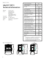
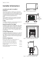
It is permitted to install the appliance against a wall 

made of combustible material with the clearances 

specified in figs. 5-6.

 

The minimum clearance to combustible material in 

front of the appliance is 6

00

 mm.

 

WARNING:

 Curtains may not be placed within 6

00

 mm 

above the appliance.

 

Never store combustible gas or liquid in the same room 

with the appliance.

 

WARNING:

 Never use the appliance if the front glass 

panel has been removed, is cracked, or is open.

 

Replacement  of the glass should be done by a licensed 

or qualified service person.  Only remove glass for rou-

tine service.  Always handle glass carefully.

 

Do not burn solid fuel in the appliance.

 

Do not place combustible material on or near the appli-

ance, as the appliance becomes hot.

 

This appliance becomes hot in use so it advisable to 

keep young children, the aged, or infirm, and animals at 

a safe distance using a fireguard conforming to BS6

539


or BS

6778

 to provide extra protection.

Summary of Contents for GF 3 BF

Page 1: ...e or other flammable vapors and liq uids in the vicinity of this or any other appliance WHAT TO DO IF YOU SMELL GAS Do not try to light any appliance Do not touch any electrical switch do not use any...

Page 2: ...ssociated with the repair of gas controls plumb ing burners log set or sheet metal firebox beyond the warranty period 5 Damage caused by unauthorized modification use or repair 6 Damage to enameled su...

Page 3: ...6 5 User Information 14 6 Troubleshooting 16 7 Parts Illustrations and Lists 19 8 Service Record 23 THIS OWNER S MANUAL PROVIDES INFORMATION TO ENSURE SAFE INSTALLATION AND EFFICIENT DEPENDABLE OPERA...

Page 4: ...Burner Injector Marking 39 53 Pilot Injector Marking 51 30 Maximum Gas Consumption at Full Rate m3 h at 15 C 1013 25mbar 0 714 0 282 Maximum Gas Consumption at Full Rate kg h at 15 C 1013 25mbar 0 53...

Page 5: ...trol cover and control switch Care should be taken not to touch unit when it is in operation WARNING If you detect an odour of gas Do not light the Stove or any other appliance Do not use electrical s...

Page 6: ...d on carpet vinyl linoleum or other combus tible material Minimum dimensions of the floor plate 580 x 435 mm as in fig 2 J tul can supply floor plates in a variety of colors Firewall Requirements The...

Page 7: ...erminal which is supplied attached with 600mm of flue pipe The 600mm terminal section may be cut to up to 300mm if required 2 Flue arrangement for horizontal termination Fig 6b When the horizontal len...

Page 8: ...ations 400mm Max This arrangement can only be made using kit M82671 The maximum permissible horizontal length is 400mm This length is supplied attached to the terminal Fig 6 a Fig 6 b Fig 6 c Fig 6 d...

Page 9: ...ngth is 600mm or less Vent restrictor position is D 2 Flue arrangement for horizontal termination when horizontal length is greater than 600mm Vent restrictor position is D 3 Flue arrangement for vert...

Page 10: ...the peg as in fig 11 3 Place the left log on the pegs as in fig 12 4 Install middle log on the appropriate pegs shown in fig 13 5 Position embers loosely and maintain 6 mm clearance from the burner sk...

Page 11: ...gure 11 Install right log Figure 12 Install left log Figure 13 Install middle log 1 4 6 mm 1 4 6 mm Pilot Assembly KEEP CARRY OVER PORTS CLEAR PN 220730 PN 220728 PN 220729 Figure 14 Spread ember ston...

Page 12: ...con nected to the appliance open the gas supply and light the appliance see lighting instructions Perform a tightness test on all the pipe connections Commissioning Testing Gas Pressure Correct gas p...

Page 13: ...Flame above 2 Cleaning the glass 3 The gasket around the glass must be inspected annu ally for wear and replaced if necessary 4 Check if the textured embers need to be replaced 5 Look for soot It cou...

Page 14: ...t the appliance may emit a harmless non toxic odour It is recommended that the room should be thoroughly ventilated by opening doors or windows during first time use The gas is not toxic but the room...

Page 15: ...paint and lubrication used in the production process See section Odours when using the stove for the first time Adjusting the Heat Setting Heat and flame size can be adjusted by turning the regu lato...

Page 16: ...t a metal piece and the control knob red mark on the spark igniter is finally pushed to the bottom B If not replace the Piezo spark ignitor Fuel Gas Correct gas pressure is important see the section a...

Page 17: ...r the valve even if the pressure is OK at outlet E You should therefore always check for leakage Thermocouple Fig 23 and Thermopile Fig 24 A thermocouple is in principle a thermal generator and consis...

Page 18: ...he ON OFF STAT switch is connected 10 Turn the control knob on the valve to ON and turn the ON OFF STAT switch to ON At this point the multi meter should show more than 300 mV 11 If a thermostat or re...

Page 19: ...3 Figure 26 NOTE THE GAS CONTROL VALVE ASSEMBLY IS MOUNTED AT THE CENTER FRONT OF ALL STOVES NOTE THE GAS CONTROL VALVE ASSEMBLY IS MOUNTED AT THE CENTER FRONT OF ALL STOVES J tul GF 3 BF 3 Illustrat...

Page 20: ...Block 220614 20 Gas Line 5 16 x 18 Flex 154372 21 Orifice Holder Straight 129643 22 Glass Gasket Replacement Kit 155599 23 Glass Panel Ceramic 220576 24 Glass Gasket 7 16 Tadpole 6 ft 129124 25 Glass...

Page 21: ...21 139405_A CF 3 BF 3 Figure 27 Approved Vent Components M82678 M82652 M82650 M82653 M82654 M82668 M87379 M87913 M82656 M82657 M30170 M82667...

Page 22: ...22 139405_A CF 3 BF 3 100 170mm L 400mm Figure 27a Approved Vent Components M82655 M82671 M87196 M82661...

Page 23: ...ervice year 4 Sign Company Date Service details Annual service year 5 Sign Company Date Service details Annual service year 6 Sign Company Date Service details Annual service year 7 Sign Company Date...

Page 24: ...continual product development Consequently products may differ in speci fication color or type of accessories from those illustrated or described in various publications March 9 2011 139405_A J tul A...

Reviews: