background image

Manual

These poles then allow for a 24dB per octave filter (4 x 6dB). The amount of filtering is

named ‘Filter slope’. A 2 pole filter has a Filter slope of 12dB, a 3 pole filter corresponds to
18dB, etc.

The Filter slope is in most filters a fixed setting and it determines the sound character of a

synth to a large extent. The higher the Filter slope, the more power the filter has. You can make
interesting sounds with less poles as well. The Filter slope is not a ”quality“ label for the filter,
instead it describes how it works. With the SUNYSN, you are given the flexibility to control
these poles i.e. the Filter slope to produce some very interesting results!

Resonance:

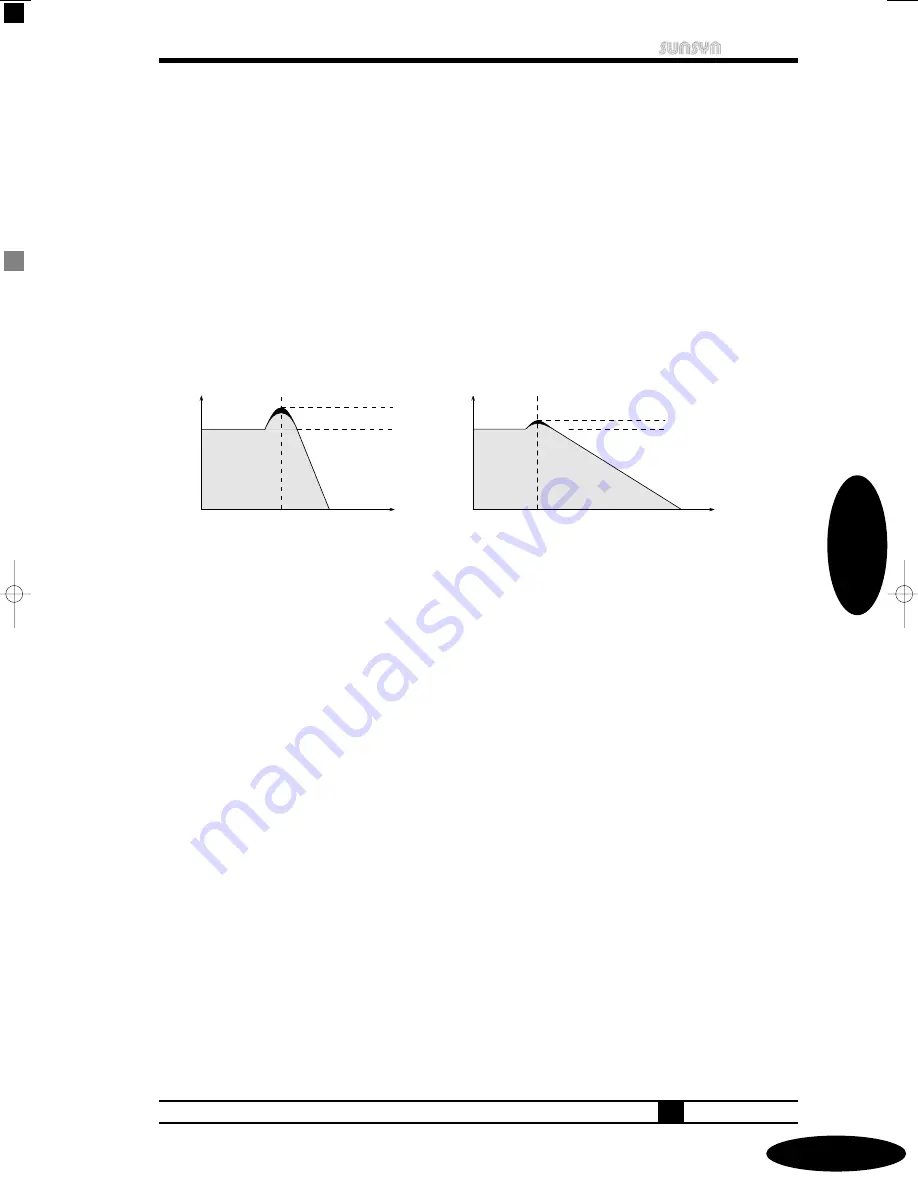
The resonance parameter is used to create a feedback loop of the frequencies near the cutoff

frequency. The sound becomes more nasal. When a lot of resonance is applied, the filter starts
to oscillate by itself (self-oscillation). A sine wave with the frequency of the filter cutoff is then
created (best known as pumping).

The higher the Filter slope (the steeper the filter curve), the more explicit the filter

resonance is. The resonance of a 6dB 1 pole filter isn’t boosted that much, even at its maximum
setting. It’ll be very hard to make it self-oscillate. On the other hand, a 24dB 4 pole filter starts
to pump even at lower resonance settings.

All these different filter types and filter characteristics allow for a different sound when

fading out different frequency ranges by different amounts.

The ”classic“ synthesizer filter is generally the 24dB Lowpass. This filter type is the most

effective and has the most pronounced resonance. The other filter types also allow for
interesting sounds and effects. In the SUNSYN, you can combine different filter types and you
can change them in a very flexible way.

Here’s a small summary of the most important filter parameters:

• Typ:

defines what frequency range is passed on (Lowpass, Highpass,
Bandpass).

• Cutoff-Frequenz:

defines at what frequency the filter starts working.

• Flankensteilheit:

defines how steep the filter curve is.

• Resonanz:

feedback loop of the frequencies near the cotuff frequency.

After this guided tour, we recommend you take a small break… OK, we said small break,
right!? ;-) Let’s take a look at the SUNSYN’s filter section!!!

VCF Filter

3-6

033

Single Mode

Resonance

4-Pole

Resonance

2-Pole

Cutoff
Frequenzy

Cutoff
Frequenzy

Level

Frequenzy

Frequenzy

Level

thebook-all  07.11.2002 18:28 Uhr  Seite 33    (Schwarz Bogen)

Summary of Contents for SUNSYN

Page 1: ......

Page 2: ...iately and consult qualified service personnel or your appropriate JoMoX dealer Make yourself familiar with the warranty claim Unplug the unit before cleaning Clean with a damp cloth only Do not spill...

Page 3: ...Midi Channels 14 2 2 Program Section 14 2 2 1 Single Sounds 15 2 2 1 1 Selecting Single Sounds 15 2 2 1 2 Editing Single Sounds 15 2 2 1 3 Storing Single Sounds 16 2 2 2 Multi Programs 16 2 2 2 1 Sele...

Page 4: ...Morph Feature 39 3 7 VCA 40 3 8 Envelopes VCA 40 3 8 1 Envelope 1 40 3 8 2 Envelope 2 40 3 9 LFOs 41 3 10 Routing Elements 44 3 10 1 Principle 44 3 10 1 1 Source 1 and 2 45 3 10 1 2 Modifier 46 3 10 1...

Page 5: ...3 11 1 1 External In 66 3 11 1 2 Card 66 3 11 1 3 Miscellaneous 67 3 11 1 4 Tuning 67 3 11 2 Arpeggiator Menu 68 3 11 3 Midi Menu 69 3 11 3 1 Channel Menu 69 3 11 3 2 Unisono Menu 70 3 11 3 3 Enable...

Page 6: ......

Page 7: ...s of the SUNSYN is the inclusion of the RCO oscillators You have access to two of these per voice 16 in total that contain digital wavefiles that can be manipulated much like wavetables but in this ca...

Page 8: ...well as the huge sonic possibilities that analog has to offer In case you ve already worked with an old analogue classic synthesizer you ll be used to the peculiarities of such a machine and you ll be...

Page 9: ...is book on the Wizoo site www wizoo de In English Electronic Music Systems Technologies and Controls written by Allen Strange ISBN 0 698 03602 2 Published by Brown Company Publ Iowa You can obtain thi...

Page 10: ...fill out your registration card yet Please send it to us Connections Input Output Power The SUNSYN accepts either 220 Volt or 110 Volt power IMPORTANT Make sure the Voltage switch is set to the correc...

Page 11: ...omputer hardware sequencer etc Connect the Midi Out or Midi Thru to the Midi In of your computer hardware sequencer etc Avoid midi loops unless you like the effect It s a rule of thumb to keep the cab...

Page 12: ......

Page 13: ...y are strictly informational at this point You can t change any settings at this screen This info page is the top level page In the next couple of paragraphs we ll explain some of the more important f...

Page 14: ...his sets the channel on which the SUNSYN sends midi information RxCh Receive Channel choose channel 1 to 16 This sets the channel on which the SUNSYN receives midi information 5 Exit the midi menu By...

Page 15: ...ee digit LED Display shows the current single sound number 001 and the LC Display indicates The lower line shows the midi receive and transmit channel the assigned audio output and the program level Y...

Page 16: ...tch single sounds Stored at the location of the current Single Sound Push the Soft Button Yes The edited sound has now been stored in the current location The original Single Sound has been overwritte...

Page 17: ...ogramm you have to enter the Multi Menu 1 Press the Menu button 2 Press the Soft Button Edit 3 Push the Soft Button Assig Assignment 4 Push the Page button LED 5 8 lights and the LC Display shows You...

Page 18: ...ton No matter which menu you are in you can go back to the top info page by pressing this button You can use the corresponding Soft Button to select a sub menu Don t panic there very few submenus Subm...

Page 19: ...menu contains global settings that are the same for all voices e g master tuning of the SUNSYN or the LC Display contrast 2 Soft Button Arpgi Let s you edit the arpeggiator settings 3 Soft Button Mid...

Page 20: ......

Page 21: ...sources Each of the VCO s has assignable modulation inputs Two RCO s Ramp Controlled Oscillator These two oscillators can play digital waveforms or short samples One Noise Generator that can produce e...

Page 22: ...s access to up to four Routing Elements allowing you to use 1 2 3 or 4 per voice Keep in mind that Routing Elements only become active once you program them so it is possible to not use any at all or...

Page 23: ...tion range is 1 octave The Cents knob can be used to fine tune VCO 2 against VCO 1 The range is one semitone Although the user interface might suggest that Semitones and Cents affect VCO 1 they only a...

Page 24: ...s pressed VCO1 will be restarted at a zero crossing every time it s triggered Due to the fact that the VCO s are real analogue they are always oscillating not only when a note is played Therefore a no...

Page 25: ...now It could be interesting e g to create a digital sound with the RCO s and then fatten it up with the VCO s The other way round you can add e g slightly detuned sinewaves from both RCO s to make so...

Page 26: ...ange of 128 to 127 The tuning happens in steps of 1 16th of a semitone This means you can tune it 8 semitones up or down This menu also consists of two pages Using the Page button you can edit further...

Page 27: ...O wave Because of the fact that these analog created waves always differ slightly and continuously a wave played by a synced RCO gets also slightly randomised and looses its originally static characte...

Page 28: ...and the VCA It can be fully treated by these modules On top of that the external signal source is also available in the Routing Element matrix Using the Routing Elements it can be inserted in the SUN...

Page 29: ...level adjustment on a mixing desk or fx unit works Setting the External Signal level The position of the Level knob also determines the volume of the external signal in relation to the other audio sig...

Page 30: ...into the External In The SUNSYN produces a sound which changes in sync to the rhythm of the drumloop e g its volume fluctuates because the envelope follower of the External In modulates the Cutoff Fre...

Page 31: ...e filter is the central element for sound creation in most synthesizers It influences the sonic characteristics of all signals Additional modules like envelopes and LFO s can be used to change the sou...

Page 32: ...range remains almost unchanged If it seems as if the filter doesn t work switch the filter type to Highpass This means that all frequencies to the left of the cutoff frequency are removed from the sig...

Page 33: ...The resonance of a 6dB 1 pole filter isn t boosted that much even at its maximum setting It ll be very hard to make it self oscillate On the other hand a 24dB 4 pole filter starts to pump even at lowe...

Page 34: ...ricted to a fixed 1 2 3 or 4 pole setting You can also set anything inbetween these standard settings To do this just set the cutoff frequency of each pole by turning the Pole knob Depending on what p...

Page 35: ...le way thereby creating many different sonic characteristics VCF Filter 3 6 035 Single Mode Level Frequenzy against each other shifted Pole Cutoff Stellung 1 Pole 2 Pole 3 Pole 4 Pole resulting Slope...

Page 36: ...s When this happens the filter works like a sinus oscillator and it produces the well known feedback pumping sound Its frequency is set by the cutoff knob The resonance intensity and the point where s...

Page 37: ...to Lowpass They filter out the high frequencies 3 Turn all four Pole knobs fully anticlockwise Each individual pole now has the same cutoff frequency The entire filter now has the steepest possible cu...

Page 38: ...ly anticlockwise or to the middle or when you turn them to whatever direction as long as all 4 poles have the same setting the filter will always be a 24dB highpass filter Only the range of the cutoff...

Page 39: ...ount Pole 1 4 and the High Lowpass settings exept on pole 4 Envelope 1 parameters Attack Decay and Sustain Try it out by loading a single sound changing the filter settings and saving the edited versi...

Page 40: ...s hardwired to the filter cutoff Envelope 2 is hardwired to the control input of the VCA This way you don t need any additional settings to program dynamic filter or level changes Next to the hardwire...

Page 41: ...ower depending on its value after releasing the key Envelope Amount Envelope amount defines how much envelope 2 affects the audio signal This value is set in the VCA section of the SUNSYN Envelope 1 E...

Page 42: ...ending saw Sudden start and slow decay Can be used for reverted echo effects D Square Starts and drops abruptly It s good for tremolos and many other things Because this waveform almost corresponds to...

Page 43: ...s have the following features 1 Soft Controller SynL1 Syncronisation Intr Internal The LFO1 speed is controlled by the internal SUNSYN clock and is adjusted with the Speed knob in the LFO Section of t...

Page 44: ...y we ll take a closer look at the Routing Elements Let s first explain what a Routing Element actually is In order to fully understand the possibilities of the Routing Elements we recommend to first r...

Page 45: ...tions between several inputs and outputs of different modules Such a cable looks like this Source 1 and 2 These act as plugs where you could drain off signals from the outputs of the modules You can d...

Page 46: ...c pheno menons and not just virtual simulations Hence the dynamics of the resulting sounds are not limited by calculation errors etc There s no difference between audio signals and control voltages Bo...

Page 47: ...is always active and allows you to assign several selectable midi controllers e g the modulation wheel aftertouch etc as well as velocity into the modulation VCO 1 B Audio Saw Signal of VCO 1 VCO 2 D...

Page 48: ...ut of the VCF This Audio input exists next to the hardwired input which mixes the audio signals into the filter VCO s RCO s Noise EXT IN It can be used when you do not want to use the hardwired input...

Page 49: ...entire signal path at a glance When pushing a button in the Routing Elements section the LC Display of the programming section will show the correct mode Setting the Modulation Routing Amount Use Sof...

Page 50: ...unt R3AMT Routing Element 3 Amount R4AMT Routing Element 4 Amount Here you can define one of the four Routing Elements of which the Routing Amount should be controlled by the above selected midi contr...

Page 51: ...est Destination Here you can select the destination parameter The same 32 destinations that were available for midi controller assignment are also selectable for velocity assignment The parameter sett...

Page 52: ...lation source The LED LFO1 lights 4 Switch off source 2 by pressing the Source2 Up Down button so that no LED of the source 2 section lights 5 Select VCF Cut as destination with the Destination Up Dow...

Page 53: ...s to try out the possibilities 13 Now the Soft Controller Curve can be used to set the curve The settings will create a different feel when playing the keys We ve now created the effect we wanted the...

Page 54: ...the cutoff control input of the VCF receives both signals the signal from the fixed signal path and the signal from the routing elements This could be compared to cabling two cables into the same inpu...

Page 55: ...VCA sections fully anticlockwise On the other hand when you create several routings that go to the same destination you ll obtain a higher signal level This means the resulting sounds will be very lou...

Page 56: ...eriment with the frequencies Range Semitones and cents to change the sonic characteristics E g when the modulating frequency source is lower than the carrier destination then inharmonic overtones and...

Page 57: ...cross modulation the output signal of oscillator 2 additionally modulates the frequency of oscillator 1 To realise this interconnection between the oscillators you need two routing elements The most s...

Page 58: ...s more lively and thick You can once again use a modifier to control the PWM intensity If you want to control the pulse width of both oscillators you need a second routing element thatcontrols the pul...

Page 59: ...routing Ringmodulation is a special form of amplitude modulation Two signals with different frequen cies are multiplied At the output of the ringmodulator you get the sum and the difference of both s...

Page 60: ...t to E g by sending the ringmodulated signal to the VCF IN you can filter it It s not modulated anymore though By sending it to destination VCO 1 FM on the other hand the ringmodulated sound will crea...

Page 61: ...IN lights 6 Press the Routing No button to select routing element 2 The corresponding LED now lights and the second routing element is now active 7 Press the Source 1 Up Down buttons to select VCO1 D...

Page 62: ...he Level knob of VCO 1 VCO 2 RCO 1 RCO 2 Noise and EXT IN to zero This way the entire audible signal is ringmodulated By opening the level knobs of the audio sources the signals are mixed together wit...

Page 63: ...less to give several routing elements the exact same signal path We want to remind you though that all signal paths in the routing elements are hardware circuitry and that all signals voltages physica...

Page 64: ...voltage which the keyboard or midi controller transmits the higher the pitch frequency The most common relation between control voltage and pitch is the octave Volt scale In this scale one octave corr...

Page 65: ...are hidden in menus We ve explained some of these features already during the description of the individual modules In this chapter we ll focus on the ones that haven t been explained yet We ve seen t...

Page 66: ...have the following features in this menu 1 Soft Controller DIR Directory This gives you a directory listing view the contents of the inserted disc Use the soft controller to scroll through the waveset...

Page 67: ...ed off When turning a knob you ll hear audible steps in the parameter changes This could be useable under some circumstances 3 Soft Controller MemPr Memory Protection on All SUNSYN parameters are writ...

Page 68: ...uences When the amount of played keys is higher than 8 the first played note will be replaced by the last one After pressing the Soft Button Arpgi in the top menu level you get to the arpeggiator menu...

Page 69: ...signal on off 3 Soft Controller Chord Chord 4 Soft Controller Mode Midi Menu All midi settings are adjusted in this menu The midi menu is divided into four submenus After pressing the Soft Button Mid...

Page 70: ...lay indicates This is the place where you can activate the Unison mode Also the midi mode can be set up here The two soft controllers have the following function 1 Soft Controller Unison Unisono Mode...

Page 71: ...ata on off 2 Soft Controller Porta Portamento Choose whether you want the SUNSYN to react to portamento data on off 3 Soft Controller Hold Hold Controller Release Time Choose whether you want the SUNS...

Page 72: ...Load Here you can load SysEx data Set the Soft Button SysEx to on Make sure the device which is going to send the data is ready to send Start the dump by pressing the Soft Button Bload The LED Display...

Page 73: ...e third software generated envelope not yet implemented The soft buttons have the following features Controller Menu Soft Button Cntrl The LC Display shows In this submenu you change the settings of t...

Page 74: ...cay time E1SUS Envelope 1 Sustain level E1REL Envelope 1 Release time E2ATT Envelope 2 Attack time E2DEC Envelope 2 Decay time E2SUS Envelope 2 Sustain level E2REL Envelope 2 Release time CUTOF Cutoff...

Page 75: ...Velocity Menu Soft Button Veloc The LC Display shows In this submenu you can assign the velocity Up to eight parameters can be controlled by velocity at the same time Here also you can assign the dest...

Page 76: ...ncreasing values exp2 exponential 2 as exp1 but less extreme Routing Elements Menu Soft Button Rout Here you get to the submenu to set the modulation amount of the 4 routing elements Please read chapt...

Page 77: ...ectly by pressing the Trigger button in the LFO section of the front panel All features are explained in chapter LFO s 2 Soft Button RCO This is the RCO menu You can also access this menu directly by...

Page 78: ......

Page 79: ...To access the top page of the multi mode menu press the Type button The LED Multi lights and the LC Display shows The upper line shows the name and the number of the multi program It also shows the p...

Page 80: ...Menu button 4 Now press the Soft Button Edit This is the selection of the several multmode submenues you can now access The Soft Buttons then have the following functions 1 Soft Button Assig Assignmen...

Page 81: ...Soft Button Name Here you can name the multi program You can do this in exactly the same way it s done for single sounds as described in chapter Menu driven features edit menu name 2 Soft Button Out...

Page 82: ...ds in a multi programm that contain active RCO s As we know the RCO s can be used in Sync Mode When a multi programm contains single sounds with active RCO Sync Mode and single sounds without RCO Sync...

Page 83: ...3 RCO 2 Level 24 VCO 1 Pulse width 25 VCO 1 Pulse width 26 Semitones 27 Cents 28 LFO 1 Speed 29 LFO 2 Speed 30 Source 1 31 Bank Select 32 ENV 1 Attack 44 ENV 1 Decay 45 ENV 1 Sustain 46 ENV 1 Release...

Page 84: ...with all of our products we intend to continuously improve the SUNSYN as much as we can This will not only make the SUNSYN a state of the art device for a long period of time but it will also make it...

Page 85: ...is remedied as quickly as possible This warranty is in addition to our general terms of business This warranty does not cover any of the following Carriage to and from the dealer or factory for inspec...

Page 86: ......

Reviews: