background image


Operation

Device setup and connection

1.  Set up the maintenance unit or secure it to the wall or workbench.

2.  Push-fit the hose for external air supply on to the maintenance unit. By briefly pulling rear-

wards, the hose is safeguarded against disconnection (Fig. 7.1).


Fig. 7.1 (symbolic drawing)

3.  After installing the hose coupling, connect the other end of this hose to an external com-

pressed-air hose.

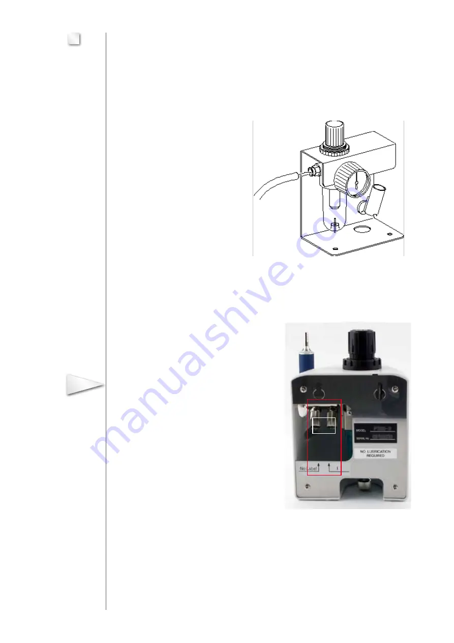
4.  Connect the two hoses of the foot switch to  

the connections (A) of the maintenance unit (Fig. 7.2).  

Unscrew the union nuts and push on to the  

hose. Push-fit the hose ends on to the  

connections before retightening the union nuts.  


In doing so, take care that the hose marked  

number 1 is located on the likewise numbered  

connection piece (1). 


Fig. 7.2       Rear view

5.  Plug the hose for the handpiece on to the maintenance unit and secure by 

pulling rearwards. Push the locking ring (Fig. 7.2/10) on to the hose beforehand. 


08


7

Important

A

Summary of Contents for 0 009 900-0

Page 1: ...Surface Technology Oberfl chentechnik Instruction Manual ENESKA P 320 2 Order No 0 009 900 0...

Page 2: ...following meaning 5 1 Figure 5 1 2 Position 2 in the key to the figure Please feel free to call our customer service department at any time should you encounter techni cal problems which are not deal...

Page 3: ...in a general apprenticeship should only be allowed to work with the machine under the constant supervision of an experienced opera tor 11 Restrain from any type of work that could jeopardise your saf...

Page 4: ...pproved for the handpiece may be used in this case Approved tools Refer to joke catalogue Grinding polishing and deburring tools Fig 5 1 High speed handpiece P 320 2 1 Head section tool receptacle wit...

Page 5: ...eparator 2 Foot switch 3 Handpiece P320 2 with rest 4 Air hose for handpiece 5 Compressed air supply hose for maintenance unit 6 Fixing screws for wall installation 7 Auxiliary tool for inserting a sh...

Page 6: ...with the smallest tool diameters The turbine drive is equipped with encapsulated bearings Additional lubrication with oil mist must not be performed Owing to the low weight of the handpiece sensitive...

Page 7: ...N cm Device control Actuation of the devive Foot switc Speed setting via pressure reducer Dimensions and weights Handpiece Diameter 16 6 mm Length 130 mm Weight without hose 70 g Length of air hose to...

Page 8: ...se to an external com pressed air hose 4 Connect the two hoses of the foot switch to the connections A of the maintenance unit Fig 7 2 Unscrew the union nuts and push on to the hose Push fit the hose...

Page 9: ...turn the controller knob to unlock After adjusting the nominal value depress the knob again to lock 3 Operate the foot switch to switch the handpiece on and off and in order to check perfect opera tio...

Page 10: ...rinding and milling with the handpiece Heavy soiling accumula ted during work may destroy the bearing and the tools Pay attention to the permitted cutting speeds and the tool manufacturer s guidelines...

Page 11: ...Replace collet Bearing turbine in head section fault Replace head section Maintenance unit faulty Replace maintenance unit Tool cannot be clam ped Collet faulty Replace collet Care Clean all parts if...

Page 12: ...ide bush and collet nut Draining condensate from the air filter 1 Render the device free of pressure 2 Loosen the union nut of the bleed valve on the condensate reservoir of the maintenance unit by un...

Page 13: ...let shaft diameter of the tool 1 6 mm The tools listed below are constantly being updated Please consult the current catalogue or the Internet or joke directly Precision diamond tools Grit D 126 Total...

Page 14: ...ne 1 60 mm x 10 0 mm 19 mm 0 560 589 Tungsten carbide burs Total length Order no Ball 1 80 mm 19 mm 0 502 201 Ball 1 80 mm 19 mm 0 502 202 Ball 2 30 mm 19 mm 0 502 203 Rounded cylinder 1 40 mm x 4 40...

Page 15: ...the following equipment as a print see above for address by fax as a pdf file to my email address Eneska high speed handpiece P320 2 Order No 0 009 900 0 Handpiece P320 2 Order No 0 009 901 Head secti...

Page 16: ...nik joke Technology GmbH Asselborner Weg 14 16 D 51429 Bergisch Gladbach Telefon 022 04 8 39 0 Telefax 022 04 8 39 60 Internet www joke de E Mail info joke de All rights reserved for modifications due...

Reviews: