background image

©2012 Johnson Level & Tool 

21

Dot Accuracy

1. With the laser on its base and set on a flat platform, turn the 

laser on.

2. Mark the down beam location and use this as your reference

point.

3. Locate the up beam and mark its point as ‘A’.

4. Rotate the laser (not moving the base) 180° by swiveling the laser

on its base and mark the up beam location as ‘B’.

5. Rotate the laser 90° and mark the up beam as ‘C’.

6. Rotate the laser 180° and mark the up beam as ‘D’.  

Note: 

Do not move the base, and always have the down beam in

the same location.

7. Connect the four dots.  Connect A to B, and C to D.

8. If the center point ‘E’ is more than 1/8” at 50’, or 1/32” at 24.5’

from points A,B, C, and D, the unit needs to be recalibrated.

Fine Calibration

1. Remove plastic screws on front and left of the laser.

2. With the unit on its base, and on a flat surface, turn the laser on.

3. Return the laser back to its original starting point from the self

check.

4. Use a 2mm allen wrench to turn the front adjusting screw to 

position the laser beam forward and backward.

5. Use the side adjusting screw to position the laser beam left 

and right.

6. Move the top beam to the intersection of the 4 dots.

6339H_Manuals  10/24/12  12:56 PM  Page 21

Summary of Contents for 40-6685

Page 1: ...Self Leveling Combination Cross Line Laser and Five Beam Laser Dot We suggest you read this instruction manual thoroughly before using the instrument Save this instruction manual for future use This i...

Page 2: ...ription for Model 40 6685 Qty Self Leveling Combination Cross Line Laser Five Beam Laser Dot 1 Multi functional Magnetic Base 1 Mounting Strap 1 AA Alkaline Batteries 3 Tinted Glasses 1 Magnetic Targe...

Page 3: ...and sounds audible alarm when the laser is beyond its self leveling range Pendulum locking mechanism helps protect units inner mechanisms Multi functional magnetic base for attaching to tripod or any...

Page 4: ...in the presence of gases or flammable liquids Keep the laser tool out of the reach of children and other untrained persons Do not attempt to view the laser beam through optical tools such as telescope...

Page 5: ...2012 Johnson Level Tool 5 4 Location Content of Warning Labels 6339H_Manuals 10 24 12 12 56 PM Page 5...

Page 6: ...er Line Output Windows Battery Cover 1 4 20 Thread Self calibration Aperture A Self calibration Aperture B Compensator Lock Unlock Switch 1 4 20 Thread attaches to base Wall Mount Belt Mounting Groove...

Page 7: ...s 1 As shown in figure open the battery cover 2 Put three AA alkaline batteries into the battery compartment noting polarity 3 Close the battery cover 7 Using the Product Place the laser on a relative...

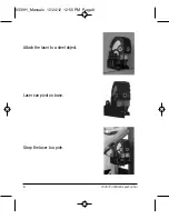
Page 8: ...8 2012 Johnson Level Tool Attach the laser to a steel object Laser can pivot on base Strap the laser to a pole 6339H_Manuals 10 24 12 12 56 PM Page 8...

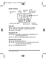
Page 9: ...er is on LED Off The laser is in self leveling mode or the laser is off Horizontal Laser Line LED LED On The horizontal laser line is on LED Flashing The horizontal laser line is in pulse mode and can...

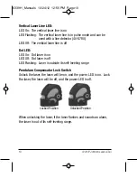
Page 10: ...On Dot laser is on LED Off Dot laser is off LED Flashing Laser is outside its self leveling range Pendulum Compensator Lock Switch Unlock the laser the laser will be on and the power LED is on Lock th...

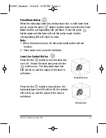
Page 11: ...e 1 When the laser lines are off the pulse mode button will not function 2 Pulse mode is for use with a detector Laser Line Control Button Press the line button to turn the laser line on or off Unlock...

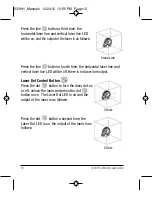
Page 12: ...ine and vertical laser line LED will be off there is no laser line output Laser Dot Control Button Press the dot button to turn the laser dot on or off unlock the laser and press the dot button once T...

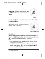
Page 13: ...de With the lasers compensator pendulum switch locked press the button or the button the laser will be in manual mode the power LED is on and the manual mode LED will be flashing Note 1 When manual mo...

Page 14: ...Sound Indicator fast tone double tone and solid tone LCD Up arrow Down arrow Center sign LED Indication Up Middle Down Dimensions 5 905 x 2 992 x 1 142 150 x 76 x 29mm Weight 0 386 lb 0 175kg Others R...

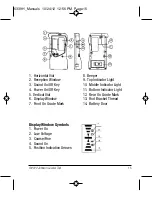
Page 15: ...Display Window 7 Front On Grade Mark 8 Beeper 9 Top Indicator Light 10 Middle Indicator Light 11 Bottom Indicator Light 12 Rear On Grade Mark 13 Rod Bracket Thread 14 Battery Door Display Window Symbo...

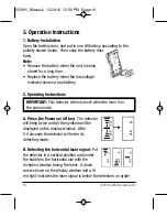
Page 16: ...rk when the laser is in the pulse mode A Press the Power on off key The detector will beep twice and all the symbols will be displayed on the display window After 0 5 seconds the detector will enter i...

Page 17: ...nd indicator lights facing up Have the reception window face the unit to receive the vertical laser signal Left arrow shown on LCD plus a lit red light indicates the laser signal is on the left side o...

Page 18: ...tone 4 Automatic Shut Off Function When not receiving a laser signal and with no operation of the keys for six continuous minutes the unit will power off automatically to preserve battery life 5 Low B...

Page 19: ...e horizontal laser line and label as M 4 Turn the instrument until the vertical line meets M and then make a mark 2 5m from M and 5m from A Label this mark as B Also make a mark on the vertical line w...

Page 20: ...rument has two calibration apertures Aperture A adjusts the horizontal axis Aperture B adjusts the Vertical axis Notes regarding adjustment 1 Use a 3mm Hexagon tool for adjustment 2 The adjustment of...

Page 21: ...beam in the same location 7 Connect the four dots Connect A to B and C to D 8 If the center point E is more than 1 8 at 50 or 1 32 at 24 5 from points A B C and D the unit needs to be recalibrated Fi...

Page 22: ...flat platform 50 from an upright wall Aim the front beam at the face of the wall Mark the point projected on the wall by front beam as A 2 Turn the instrument clockwise Fig 2 to make the point project...

Page 23: ...60m for dots depending upon light conditions Exterior Range Up to 300 ft 90m with detector included with 40 6687 Self Leveling Range 4 Power Supply 3 AA alkaline batteries included Battery Life Appro...

Page 24: ...on Level Tool 10 Application Demonstrations Reference for baseboard installation Reference for vertical partition Aligning doors and windows Reference for fence installation 6339H_Manuals 10 24 12 12...

Page 25: ...on each of its products You can obtain a copy of the limited warranty for a Johnson Level Tool product by contacting Johnson Level Tool s Customer Service Department as provided below or by visiting o...

Page 26: ...l Tool s Customer Service Department at 800 346 6682 13 Warranty Registration Enclosed with this instruction manual you will find a warranty registration card to be completed for your product You will...

Page 27: ...y applicable limited warranty and there will be NO WARRANTY If you need any assistance in locating any accessories please contact our Customer Service Department In the U S contact Johnson Level Tool...

Page 28: ...28 2012 Johnson Level Tool 6339H_Manuals 10 24 12 12 56 PM Page 28...

Reviews: