background image

3

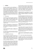
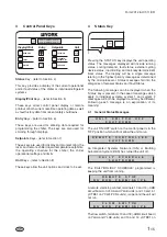
Control Panel Keys

Status

Key - (refer to Section 4)

This key provides a display of the current operational
and/or fault status of the chiller or individual refrigerant
systems.

Display/Print

Keys - (refer to Section 5)

These keys allow control panel display or remote
printout of both current real-time operating data as well
as fault history data from recent safety shutdowns.

Entry

Keys - (refer to Section 6)

These keys are used for entering data required for
programming the chiller. The keys are also used for
scrolling through displays.

Setpoints

Keys - (refer to Section 7)

These keys are used for display and programming: the
local and remote chilled liquid temperature setpoints;
the operating schedule for the chiller; the chiller
operational settings and limits.

Unit

Keys - (refer to Section 8)

These keys allow the unit options and clock to be set.

4

Status Key

Pressing the ‘STATUS’ key displays the unit operating
status. The messages displayed will include running
status, cooling demand, fault status, external cycling
device status, load limiting and anti-recycle/coincident
timer status. The display will be a single message
relating to the highest priority message as determined
by the microprocessor. Status messages fall into the
categories of General Status and Fault Status.

The following messages can be displayed when the
'Status' key is pressed. In the case of messages which
apply to individual systems, system 1 and system 2
messages will both be displayed and may be different.
Following each message is an explanation of its
meaning:

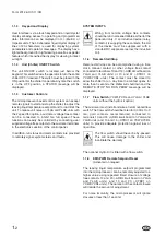
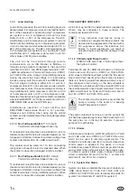
4.1

General Status Messages

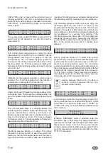
The unit 'ON/OFF' switch on the control panel is in the
'OFF' position which will not allow the unit to run.

An Integrated Systems Network (ISN) or Building
Automation System (BAS) has turned the unit off.

The 'DAILY/HOLIDAY SCHEDULE' programmed is
keeping the unit from running.

A remote start/stop contact, terminals 13 and 14 (-ARB
circuit board on YLAA and YLAE units) and 13 and 51
(-XTBC1 on YCWL/YCRL units), is open and the unit will
not run.

The flow switch, terminals 13 and 18 (-ARB circuit board
on YLAA and YLAE units) and 13 and 14 (-XTBC1 on

1

-

15

Form 201.26.OI1(11/09)

OPER DATA

SETPOINTS

PRINT

SCHEDULE/
ADVANCE DAY

HISTORY

PROGRAM

Unit

Setpoints

Entry

Display/Print

ENTER

/ADV

OPTIONS

CLOCK

STATUS

S Y S

1

COMP S RUN

2

S Y S

2

COMP S RUN

1

U N I

T

S W I

T C H

O F F

S H U T D O W N

R E M O T E

C O N T R O L L E D

S H U T D O W N

D A I

L Y

S C H E D U L E

S H U T D O W N

R E M O T E

S T O P

N O

R U N

P E R M I

S S I

V E

F L O W

S W I

T C H

N O

R U N

P E R M I

S S I

V E

Summary of Contents for York YCRL0200HE

Page 1: ...WL0240SE YCWL0395SE YCWL YCRL0200HE YCWL YCRL0610HE OPERATING INSTRUCTION Form 201 26 OI1 11 09 035 21976 110 Revision 1 R410A Tempo Zafiro AIR WATER COOLED LIQUID CHILLERS MICRO BASED CONTROL SYSTEM...

Page 2: ......

Page 3: ...ey 4 1 General Status Messages 1 15 4 2 Fault Status Messages 1 17 5 Display Print Keys 5 1 OPER DATA Key 1 19 5 2 PRINT Key 1 22 5 3 History Key 1 24 5 3 1 Clearing History Buffers 1 24 5 3 2 History...

Page 4: ...OPER DATA Key 1 45 15 3 SETPOINTS Key 1 45 15 4 Leaving Liquid Temperature Control 1 45 15 5 BAS EMS Temperature Reset Voltage Current Signal 1 46 15 5 1 0 10 Vdc Remote Signal 1 46 15 5 2 2 10 Vdc Re...

Page 5: ...e analog inputs digitizes them and constantly scans them to keep watch on the unit operating conditions The input values are transmitted serially to the IPU II microprocessor board From this informati...

Page 6: ...able earthed at the panel end only If an inductive device relay contactor is supplying these contacts the coil of the device must be suppressed with a standard RC suppresser across the inductive coil...

Page 7: ...S LIQUID PUMP START CONTACTS SYSTEM 2 ALARM STATUS LK F1 RU RP FSI PWM XTBC2 XTBC1 ARB ARB YLAA Customer Controls 3 4 REMOTE EMERGENCY STOP DEVICE 14 16 13 13 13 18 FLOW SWITCH REMOTE START STOP 1st S...

Page 8: ...eed Fans only To reduce unit noise the fans can be limited to run at a maximum step of all fans in star reduced speed i e fan full speed is inhibited Connect a customer voltage free contact to termina...

Page 9: ...as the lead system However the lead system must be running for a minimum of 5 minutes before the lag system will be allowed to run As the load decreases below the SETPOINT the compressors will be shut...

Page 10: ...me number of compressors running the lead system will load On units without soft start the strategy for compressor loading within a system is to maximize individual compressor run time and ensure that...

Page 11: ...60 second time delay will always separate motor starts This timer is not programmable 2 4 Compressor Crankcase Heater Each compressor is fitted with a crankcase heater not controlled by the micro proc...

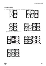
Page 12: ...elow YLAA MODEL SYSTEM 1 SYSTEM 2 0180SE to 320SE 0195HE to 0260HE 2 2 0360SE 0400SE 0300HE 3 2 0390HE 4 2 0435SE 0485SE 0350HE 3 3 0440HE 4 3 0455HE 0515HE 4 4 YLAE MODEL SYSTEM 1 SYSTEM 2 0190SE to...

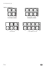
Page 13: ...F2 1 MF2 1 MF1 CONTROL PANEL 2 MF1 1 MF2 2 MF2 1 MF1 CONTROL PANEL 2 MF1 2 MF2 1 MF2 1 MF1 CONTROL PANEL 2 MF1 2 MF2 1 MF4 1 MF3 2 MF3 1 MF2 1 MF1 CONTROL PANEL YLAA 180SE 195HE 210SE YLAA 350HE 435SE...

Page 14: ...5HE to 0510HE 2 MF2 2 MF1 1 MF2 1 MF1 YLAE 0190SE to 0330SE YLAE 0195HE to 0265HE 2 MF3 2 MF2 2 MF1 1 MF3 1 MF2 1 MF1 YLAE 0375SE to 0490SE YLAE 0355HE to 0405HE 2 MF2 2 MF1 1 MF3 1 MF2 1 MF1 YLAE 031...

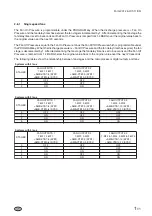
Page 15: ...ramped from 1 4 BARG below the original value back to the original value over the next 20 seconds The following tables show the relationship between fan stages and the microprocessor digital outputs...

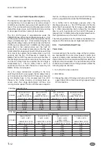
Page 16: ...e PROGRAM key On a further fall in discharge pressure when the discharge pressure is Fan Off Pressure and the fan delay timer has expired the fan stage is decremented by 1 After decrementing the fan s...

Page 17: ...SLOW 4 FAST FAST Fan Operation Stages Systems with 3 fans 1 MF1 1 MF2 1 MF3 2 MF1 2 MF2 2 MF3 0 OFF OFF 1 SLOW OFF 2 OFF SLOW 3 SLOW SLOW 4 FAST FAST Fan Operation Stages Systems with 4 fans 1 MF1 1...

Page 18: ...time and ensure that the same compressor does not start twice in a row This is achieved by rotating the lead lag sequence of the compressors in a system when a compressor other than the lag most comp...

Page 19: ...s determined by the microprocessor Status messages fall into the categories of General Status and Fault Status The following messages can be displayed when the Status key is pressed In the case of mes...

Page 20: ...if the system is fully loaded and will shut only one compressor off Discharge limiting will prevent the last compressor in a system from starting if the discharge pressure is above 85 of the programme...

Page 21: ...the cut out point is ramped up to the programmed cut out point If at any time during this 3 minutes the suction pressure falls below the ramped cut out point the system will stop This cut out is ignor...

Page 22: ...ounting down unless MANUAL POWER FAIL RESTART is programmed under the OPTION key In this case the unit switch must be set to OFF then back to ON to reset this trip YLAA and YLAE Units with Optional Hy...

Page 23: ...lay Print keys allow the user to retrieve system and unit information that is useful for monitoring chiller operation diagnosing potential problems troubleshooting and commissioning the chiller System...

Page 24: ...out the pump is started by closing a contact terminals 23 and 24 on ARB circuit board on YLAA and YLAE units and 23 and 24 on XTBC2 on YCWL YCRL units if there is a Leaving Liquid Temperature Cutout o...

Page 25: ...ts with 2 fans per system will be The message on units with 3 fans per system will be The message on units with 4 fans per system will be Where the fan status of each fan can be OFF SLOW or FAST The Y...

Page 26: ...CUTOUT 38 6 BARG SUCT PRESS CUTOUT 5 59 BARG LOW AMBIENT CUTOUT 3 9 DEGC LEAVING LIQUID CUTOUT 3 0 DEGC ANTI RECYCLE TIME 600 SECS FAN CONTROL ON PRESS 23 1 BARG FAN DIFF OFF PRESS 5 5 BARG NUMBER OF...

Page 27: ...uffer header printout is shown opposite 1 23 Form 201 26 OI1 11 09 YORK INTERNATIONAL CORPORATION MILLENNIUM LIQUID CHILLER SAFETY SHUTDOWN NUMBER 1 SHUTDOWN 8 46AM 11 APR 08 SYS 1 LOW SUCTION PRESS S...

Page 28: ...re used to scroll forwards and backwards through the history buffer to display the shutdown conditions The history data messages are shown below in the order that they are displayed 1 24 Form 201 26 O...

Page 29: ...R A T O R W A T E R P U M P S T A T U S I S O N OR for YLAA YLAE units with Hydro Kit Option E V A P O R A T O R W A T E R P U M P S T A T U S Y Y Y Y YYYY ON OFF TRIP E V A P O R A T O R W A T E R P...

Page 30: ...ETPOINTS KEYS Programming and viewing the cooling setpoints daily schedule and safeties is accomplished by using the SETPOINTS keys 7 1 Cooling Setpoints The cooling SETPOINT and RANGE can be viewed o...

Page 31: ...ture is provided for starting and stopping the chiller on individual days of the week eliminating the need for an external time clock Also provided are a holiday feature allowing special start stop ti...

Page 32: ...protects the chiller from an evaporator freeze up If the suction pressure drops below the cutout point the system will shut down There are some exceptions when the suction pressure is permitted to tem...

Page 33: ...rate sensitivity as programmed above is used Above this range a fixed 1 7 C min is used Loading is prevented if the leaving water temperature is falling faster than the RATE SENSITIVITY value On unit...

Page 34: ...er Glycol 240 s 600 s 600 s 600 600 Fan Control On Pressure YLAA YLAE units only Water Glycol 20 0 barg 33 4 barg 23 0 barg 23 1 barg Fan Differential Off Pressure 1 YLAA YLAE units only Water Glycol...

Page 35: ...can be controlled Leaving Liquid Setpoint Load Limit and Mode Cooling or Heating If the unit receives no valid ISN transmission for 5 minutes it will revert back to the locally programmed values Displ...

Page 36: ...ydro kit with single or dual pumps is used YLAA and YLAE units only When the dual pump YORK Hydro Kit Option is fitted one of the above selections can be made When AUTOMATIC is selected the DUTY PUMP...

Page 37: ...e should be correct To change the day time and date press the CLOCK key The display will show The cursor is positioned under the day Pressing the UP ARROW or DOWN ARROW will change the day The ENTER A...

Page 38: ...arting when the unit power is first turned on IMPORTANT During commissioning or if the soft start is replaced the following procedure MUST BE PERFORMED 1 With the unit switch and unit switch disconnec...

Page 39: ...URE 1 BDP 12 J7 12 NOT USED NU J8 1 2 3 0V J8 4 5 6 5V 13 J8 7 NOT USED NU 14 J8 8 NOT USED NU 15 J8 9 LEAVING LIQUID TEMPERATURE HOT YCWL units only BLHT J9 1 2 3 4 7 9 0V J9 5 6 8 5V 16 J9 10 SYS 2...

Page 40: ...ALVE 2 LLSV 10 XTB10 4 AMB K19 SYS 2 COMPRESSOR 2 2 KM2 11 XTB10 5 AMB K20 SYS 2 COMPRESSOR 3 2 KM3 XTB10 6 12 XTB10 7 AMB K21 NOT USED 13 XTB10 8 AMB K22 NOT USED 14 XTB10 9 AMB K23 NOT USED 15 XTB10...

Page 41: ...dhered to Failure to do so may result in improper printer and or chiller operation n Maximum cable length between the printer and the Microprocessor Board is 7 5 m Twisted pair shielded cable is requi...

Page 42: ...s REM C SP XXX C The analogue input is only read for a fixed interval This is normally factory set to 5 minutes 12 1 0 10 Vdc Remote Signal Jumper JP on the I O board must be set to 10 V To calculate...

Page 43: ...ding back control to the panel by sending 99 on ISN page 03 The EMS PWM remote temperature reset value at terminals 13 20 on XTBC1 will reset the chilled liquid SETPOINT based on the length of time th...

Page 44: ...el P07 START STOP COMMAND P10 HISTORY BUFFER REQUEST P06 ISN PAGE TYPE DATA P11 ANALOG LEAVING CHILLED LIQUID TEMP P12 ANALOG RETURN CHILLED LIQUID TEMP YLAA YCWL only P13 ANALOG LEAVING HOT LIQUID TE...

Page 45: ...ANTI RECYCLE TIMER ACTIVE 12 MANUAL OVERRIDE 13 SUCTION LIMITING 14 DISCHARGE LIMITING 16 LOAD LIMITING 17 COMPRESSOR S RUNNING P57 59 FAULT CODE 0 NO FAULT 1 VAC UNDERVOLTAGE 2 LOW AMBIENT TEMPERATUR...

Page 46: ...1 42 Form 201 26 OI1 11 09 DE MODIFIER ADDRESS XXXXX DE MODIFIER OFFSET XX P1 PROTOCOL XXXXXX P1 MANUAL MAC ADDRESS XXX P1 BAUD RATE XXXXX P1 PARITY XXXXX P1 STOP BITS X P2 PROTOCOL XXXXXXXXXX P2 MAN...

Page 47: ...eal Time Error NO YES None P2 Baud Rate P2 Parity None Even Odd Ignore Selectable None Even Odd Ignore Selectable P2 Protocol TERMINAL UNAVAIL MODBUS IO MODBUS SERVER API MODBUS CLIENT Selectable P1 P...

Page 48: ...REM_SP_S1 NOT USED 3 LOAD_LIMIT LOAD LIMIT STAGE 0 1 2 4 REM_CR COOLING RANGE NOT USED 5 SP_REM_SP_S2 SYS 2 NOT USED HEATING SETPOINT 30 C 52 C 537 2 Handback to panel when under options display units...

Page 49: ...T USED 24 NUM_COMPS NUMBER OF COMPRESSORS 25 S1_OP_CODE SYS 1 OPERATIONAL CODE 26 S1_FLT_CODE SYS 1 FAULT CODE 27 S2_OP_CODE SYS 2 OPERATIONAL CODE 28 S2_FLT_CODE SYS 2 FAULT CODE 29 S1_DBG_CODE NOT U...

Page 50: ...erature Hot LLTH and the Return Liquid Temperature Hot RLTH when the optional temperature sensors are fitted 15 3 SETPOINTS Key When CHILLER MODE is selected the following setpoint displays are as for...

Page 51: ...wnwards from the manually entered setpoint by using a remote 0 10 Vdc or 2 10 Vdc or 0 20 ma or a 4 20 mA signal connected to terminal block XTBC1 terminals A and A Whenever a reset is called for by t...

Page 52: ...tion Local Remote is set to Remote and the ISN is not handing back control to the panel by sending 99 on ISN page 05 The EMS PWM remote temperature reset value at terminals 13 20 on XTBC1 will reset t...

Page 53: ......

Page 54: ......

Page 55: ......

Page 56: ...Subject to change without notice ALL RIGHTS RESERVED Form 201 26 OI1 11 09 Part 035 21976 110 Rev 1 www johnsoncontrols com...

Reviews: