Johnson Controls VRF Smart Gateway Installation Instructions Manual Download Page 7

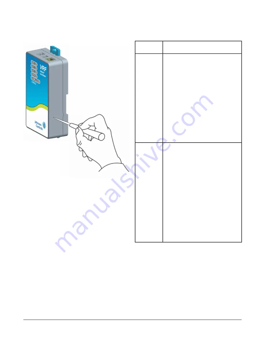
Figure 8: Using the Reset Button

Table 1: Reset Button Operation and Descriptions

Reset Operation

2

Reset
Function

1.

Press and hold the reset button for 2
seconds. The Fault LED displays Slow
Flicker behavior.

2.

Release the reset button within 3
seconds. The Fault LED continues Slow
Flicker behavior.

3.

Within 5 seconds, press the reset button
again, and then immediately release it to
confirm that you wish to reset Wi-Fi and
Ethernet settings. (If you do not press the
reset button to confirm within 5 seconds,
the reset operation is cancelled.)
The Wi-Fi (SSID and passphrase) and
Ethernet settings are reset to factory
defaults. The LEDs stop flickering for 2
seconds, and then the LEDs return to
normal operation, based on the current
state of the device.

Reset Wi-Fi
and Ethernet
Settings

1.

Press and hold the reset button for 6
seconds. After 2 seconds, the Fault LED
displays Slow Flicker behavior. This
changes to Fast Flicker behavior after an
additional 4 seconds of holding the reset
button.

2.

Release the reset button within 3 seconds
of seeing Fast Flicker behavior. The Fault
LED continues Fast Flicker behavior.

3.

Within 5 seconds, press the reset button
again, and then immediately release it to
confirm that you wish to reset to factory
defaults. (If you do not press the reset
button to confirm within 5 seconds, the
reset operation is cancelled.)

4.

All unit settings are reset to factory
defaults. The LEDs stop flashing for 2
seconds, and then the LEDs return to
normal operation, based on the current
state of the device.

Reset to
Factory

Defaults

1

1

Resets all unit settings, including user profiles.

2

For information on LED designations and flicker behavior,
see

Table 2

.

7

VRF Smart Gateway Installation Instructions

Summary of Contents for VRF Smart Gateway

Page 1: ...to be up to 30 m 100 ft line of sight away Power must be supplied using the provided external power supply North American Emissions Compliance United States This equipment has been tested and found to...

Page 2: ...unit upside down which puts the labels upside down Location Considerations Observe the following guidelines when mounting a VRF Smart Gateway Mount the VRF Smart Gateway in areas free of corrosive vap...

Page 3: ...ace to which the unit is mounted The screw holes on the VRF Smart Gateway can accommodate M3 5 and 6 screws For information on location considerations for maximizing signal strength see the Mounting s...

Page 4: ...h you are connecting Wiring the H Link Network To wire the H Link Network of the VRF Smart Gateway Connect the two H Link cable wires to the left terminals indicated in the following figure If the VRF...

Page 5: ...ne disconnection or isolation may be required to completely de energize equipment Contact with components carrying hazardous voltage can cause electric shock and may result in severe personal injury o...

Page 6: ...overed VRF devices A software update may be available for your device Visit VRFPro com or contact your nearest Johnson Controls representative for the latest version Refer to the VRF Smart Gateway Use...

Page 7: ...Fi and Ethernet Settings 1 Press and hold the reset button for 6 seconds After 2 seconds the Fault LED displays Slow Flicker behavior This changes to Fast Flicker behavior after an additional 4 second...

Page 8: ...sion On Steady Green Ethernet Off No Wi Fi signal or no devices currently connected over Wi Fi Wi Fi strength is indicated by the number of LEDs that are lit with one lit LED indicating weak wireless...

Page 9: ...the corrupted key or certificate to be saved The server detects the error and returns the Error Saving SSL Settings message While this correctly prevents the bad key or certificate from being used it...

Page 10: ...d Access Pre Shared Key mode Temporal Key Integrity Protocol WPA2 EAP PEAP WPA2 EAP TLS Wireless Security One H Link port 4 pin port Network and Serial Interfaces 145 4 x 85 4 x 40 1 mm 5 72 x 3 36 x...

Page 11: ...1 ETSI EN301 489 3 Class 2 IEC 60730 1 EN 60730 1 1 Last digit x represents non US country requirements The performance specifications are nominal and conform to acceptable industry standard For appli...

Page 12: ...Fan Dry Cool Status MI Actual System Mode SYSTEM S 25 High Medium Low Status MI Actual Supply Fan Speed SF SPD 26 50 99 C 58 210 F Value AI Zone Temperature ZN T 27 Dirty Clean Status BI Filter Statu...

Page 13: ...e INV HRS 11 0 655 350 Hours Value AI Compressor 2 Runtime COMP HRS 12 0 255 Hz Value AI Inverter Compressor Frequency INV FREQ 13 0 65 535 Hz Value AI Total Frequency TOTAL FREQ 14 0 100 Value AI Out...

Page 14: ...s Enum Value Thermo off 1 Pump down 2 SW on start 3 Thermo on start 4 After defrost 5 Start control 1 6 Start control 2 7 Normal 8 Oil return 9 Defrost ready 1 10 Defrost ready 2 11 Differential press...

Page 15: ...f synchronism 21 Na4 22 Na5 23 Normal acceleration 24 Normal deceleration 25 Constant speed 26 Overload after the acceleration 27 Overload after the deceleration 28 Overload after constant speed 29 Po...

Page 16: ...NO 22 BLOCK D NEW DISTRICT WUXI JIANGSU PROVINCE 214142 CHINA JOHNSON CONTROLS 507 E MICHIGAN ST MILWAUKEE WI 53202 USA JOHNSON CONTROLS WESTENDHOF 3 45143 ESSEN GERMANY Building Technologies Solutio...

Reviews: