Johnson Controls VRF Smart Gateway Installation Instructions Manual Download Page 5

External Power Supply Connections

To connect the VRF Smart Gateway using the supplied
external power source:

1. Connect the 15 VDC output connector of the power

supply to the power supply port of the VRF Smart
Gateway.

Risk of Property Damage.

Do not apply power to

the system before checking all wiring connections.
Short-circuited or improperly connected wires may
result in permanent damage to the equipment.

MISE EN GARDE:

Risque de dégâts matériels.

Ne pas mettre le

système sous tension avant d'avoir vérifié tous les
raccords de câblage. Des fils formant un court-circuit
ou connectés de façon incorrecte risquent
d'endommager irrémédiablement l'équipement.

2. Connect the power supply to the supplied power cord.

3. Plug the power cord into a 100 to 240 VAC outlet.

Important:

Power should only be applied and removed
by connecting and disconnecting the power
cord from the 100 to 240 VAC outlet.
Applying or removing power by connecting
or disconnecting the 15 VDC connector can
damage the unit.

Risk of Electric Shock.

Disconnect or isolate all power

supplies before making electrical connections. More than
one disconnection or isolation may be required to
completely de-energize equipment. Contact with
components carrying hazardous voltage can cause
electric shock and may result in severe personal injury
or death.

AVERTISSEMENT:

Risque de décharge électrique.

Débrancher ou isoler

toute alimentation avant de réaliser un branchement
électrique. Plusieurs isolations et débranchements sont
peut-être nécessaires pour -couper entièrement
l'alimentation de l'équipement. Tout contact avec des
composants conducteurs de tensions dangereuses
risque d'entraîner une décharge électrique et de
provoquer des blessures graves, voire mortelles.

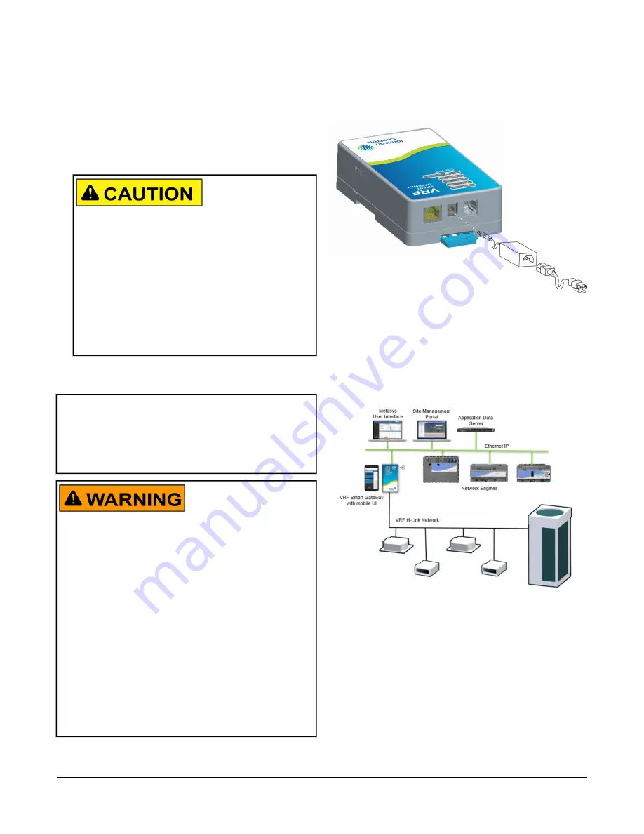
Figure 6: VRF Smart Gateway with Sample External

Power Supply

Operation

The easiest way to initially configure the VRF Smart
Gateway is by connecting to the gateway's Wi-Fi network.

Figure 7: Connecting VRF Equipment to the Metasys

System

Connecting to the VRF Smart Gateway
Wi-Fi Network

1. In the Wi-Fi settings of your device or laptop, connect

to the VRF Smart Gateway Wi-Fi network using your
default credentials. These credentials are included
on a label in the

VRF Smart Gateway Quick Start

Guide (Part No. 24-10737-156)

that came with your

device.

2. Direct your browser to

www.myvrfsg.com

to open

the VRF Smart Gateway browser interface.

5

VRF Smart Gateway Installation Instructions

Summary of Contents for VRF Smart Gateway

Page 1: ...to be up to 30 m 100 ft line of sight away Power must be supplied using the provided external power supply North American Emissions Compliance United States This equipment has been tested and found to...

Page 2: ...unit upside down which puts the labels upside down Location Considerations Observe the following guidelines when mounting a VRF Smart Gateway Mount the VRF Smart Gateway in areas free of corrosive vap...

Page 3: ...ace to which the unit is mounted The screw holes on the VRF Smart Gateway can accommodate M3 5 and 6 screws For information on location considerations for maximizing signal strength see the Mounting s...

Page 4: ...h you are connecting Wiring the H Link Network To wire the H Link Network of the VRF Smart Gateway Connect the two H Link cable wires to the left terminals indicated in the following figure If the VRF...

Page 5: ...ne disconnection or isolation may be required to completely de energize equipment Contact with components carrying hazardous voltage can cause electric shock and may result in severe personal injury o...

Page 6: ...overed VRF devices A software update may be available for your device Visit VRFPro com or contact your nearest Johnson Controls representative for the latest version Refer to the VRF Smart Gateway Use...

Page 7: ...Fi and Ethernet Settings 1 Press and hold the reset button for 6 seconds After 2 seconds the Fault LED displays Slow Flicker behavior This changes to Fast Flicker behavior after an additional 4 second...

Page 8: ...sion On Steady Green Ethernet Off No Wi Fi signal or no devices currently connected over Wi Fi Wi Fi strength is indicated by the number of LEDs that are lit with one lit LED indicating weak wireless...

Page 9: ...the corrupted key or certificate to be saved The server detects the error and returns the Error Saving SSL Settings message While this correctly prevents the bad key or certificate from being used it...

Page 10: ...d Access Pre Shared Key mode Temporal Key Integrity Protocol WPA2 EAP PEAP WPA2 EAP TLS Wireless Security One H Link port 4 pin port Network and Serial Interfaces 145 4 x 85 4 x 40 1 mm 5 72 x 3 36 x...

Page 11: ...1 ETSI EN301 489 3 Class 2 IEC 60730 1 EN 60730 1 1 Last digit x represents non US country requirements The performance specifications are nominal and conform to acceptable industry standard For appli...

Page 12: ...Fan Dry Cool Status MI Actual System Mode SYSTEM S 25 High Medium Low Status MI Actual Supply Fan Speed SF SPD 26 50 99 C 58 210 F Value AI Zone Temperature ZN T 27 Dirty Clean Status BI Filter Statu...

Page 13: ...e INV HRS 11 0 655 350 Hours Value AI Compressor 2 Runtime COMP HRS 12 0 255 Hz Value AI Inverter Compressor Frequency INV FREQ 13 0 65 535 Hz Value AI Total Frequency TOTAL FREQ 14 0 100 Value AI Out...

Page 14: ...s Enum Value Thermo off 1 Pump down 2 SW on start 3 Thermo on start 4 After defrost 5 Start control 1 6 Start control 2 7 Normal 8 Oil return 9 Defrost ready 1 10 Defrost ready 2 11 Differential press...

Page 15: ...f synchronism 21 Na4 22 Na5 23 Normal acceleration 24 Normal deceleration 25 Constant speed 26 Overload after the acceleration 27 Overload after the deceleration 28 Overload after constant speed 29 Po...

Page 16: ...NO 22 BLOCK D NEW DISTRICT WUXI JIANGSU PROVINCE 214142 CHINA JOHNSON CONTROLS 507 E MICHIGAN ST MILWAUKEE WI 53202 USA JOHNSON CONTROLS WESTENDHOF 3 45143 ESSEN GERMANY Building Technologies Solutio...

Reviews: