background image


T

6

0

0

_

T

E

C

_

R

e

m

o

v

e

_

C

o

v

e

r


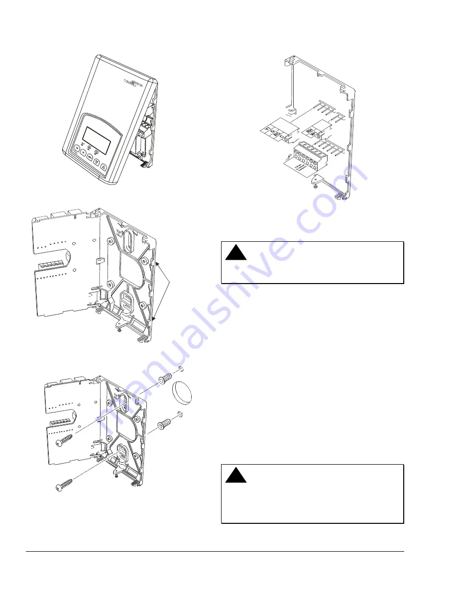
Figure 1: Removing the Thermostat Cover 

PCB

Locking Tabs

T

6

0

0

_

T

E

C

_

O

p

e

n

m

_

S

ta

t


Figure 2: Opening the Thermostat PCB 

T

6

0

0

_

T

E

C

_

M

o

u

n

ti

n

g

_

B

a

s

e


Figure 3: Mounting the Thermostat Base 

T

6

0

0

_

T

E

C

_

T

e

rm

in

a

l_

B

lo

c

k

s


Figure 4: Removing the Terminal Blocks 

Wiring 

!

  CAUTION:  Risk of Electric Shock.


Disconnect power supply before making electrical 
connections to avoid electric shock.


Note: 

When replacing an existing thermostat, 

remove and label wires to identify terminal 
designations. When replacing a T600MSP thermostat, 
simply remove the terminal blocks and reinsert on to 
the new thermostat. 

To wire the thermostat: 

1.  Strip each wire 1/4 in. (6.35 mm) and connect to 

the appropriate terminal according to the wiring 
diagram (Figure 5). 

2.  Gently push excess wire back into wall, plug the 

wall hole with fireproof material to prevent drafts 
from affecting ambient temperature readings, and 
install screw terminal blocks back onto the PCB. 

3.  Reattach the thermostat cover to the installed 

base (top side first) and install the security screw 
on the bottom. 

!

  CAUTION:  Risk of Property Damage. 

Do not apply power to the system before checking 
all wiring connections. Short circuited or improperly 
connected wires may result in permanent damage to 
the equipment. 

2    

T600MSP-2 Programmable Thermostat Installation Instructions 

Summary of Contents for T600MSP-2

Page 1: ...t cover Figure 1 2 Unlock the Printed Circuit Board PCB by carefully pressing the locking tab to the right Figure 2 Open the thermostat s PCB to the left 3 Pull out approximately 6 in 152 mm of wires...

Page 2: ...s and reinsert on to the new thermostat To wire the thermostat 1 Strip each wire 1 4 in 6 35 mm and connect to the appropriate terminal according to the wiring diagram Figure 5 2 Gently push excess wi...

Page 3: ...the selected fan mode 24 VAC from equipment transformer 24 VAC common from equipment transformer 24 VAC for heating stages Energizes on a call for first stage heating Energizes on a call for second s...

Page 4: ...and to advance to the next menu item MENU key to access the Main User Menu or exit the menu UP DOWN arrow keys to adjust values activate a Temporary Setpoint Configuration Key T600_TEC_Config_Key Fig...

Page 5: ...ver and press the CONFIG key from the Status Display Menu to enter the Installer Configuration Menu Configures Digital Input 1 Default No Function None See the Configuring the Digital Inputs DI1 and D...

Page 6: ...hen the message displays the backlight momentarily lights up TOccTime set Y N Each digital input can be programmed in one of five conditions None No function is associated with the input Service A Ser...

Page 7: ...e the Enabling Frost Protection Frost pr section for setup instructions Enabling Frost Protection Frost pr Frost protection establishes a minimum heating setpoint of 42 F 5 5 C to prevent freezing in...

Page 8: ...rature control but could accelerate the wear of mechanical components in the equipment To set the maximum number of heating cycles per hour while in the Installer Configuration Menu 1 Answer NO to all...

Page 9: ...emporary setpoint is entered The range is adjustable from 0 to 12 hours To change the temporary occupancy time while in the Installer Configuration Menu 1 Answer NO to all prompts until the temporary...

Page 10: ...lue The display now shows the cooling lockout prompt See the Setting the Cooling Lockout C lock section for instructions Setting the Cooling Lockout C lock This feature disables cooling operation base...

Page 11: ...o the beginning of the menu digital input configuration Operation Programming Operating the T600MSP 2 Once the T600MSP 2 thermostat is configured through the Installer Configuration Menu the thermosta...

Page 12: ...does not appear Answering YES to this prompt enables the T600MSP 2 thermostat to resume the regular scheduled program and setpoints Schedule set Y N To resume the schedule while in the Main User Menu...

Page 13: ...setpoints remain in effect for the duration set in the Temporary Occupancy Time parameter TOccTime or until manually released To release the temporary setpoint sooner while in the main User Menu 1 An...

Page 14: ...ys changes the time in 1 minute increments Holding the keys down changes the time in 30 minute increments Note Programming one of the digital inputs to remote NSB disables the menu Follow the steps in...

Page 15: ...e scheduling menu Press YES to set the schedule for Monday or NO to advance to Tuesday Press YES to set the occupied start time for Monday or NO to advance to Tuesday selecting NO leaves the thermosta...

Page 16: ...press YES to store the time 4 Press YES to enter the day set menu or NO to enter the clock format menu 5 Use the UP DOWN arrow keys to adjust the day When the correct day is displayed press YES to st...

Page 17: ...al Accessories Includes Mounting Hardware 2 Use the UP DOWN arrow keys to locate the desired permanent hold type or resume schedule Press YES to enter the choice Item Product Code Number Remote Indoor...

Page 18: ...pment has been tested and found to comply with the limits for a Class A digital device and verified to Class B pursuant to Part 15 of FCC Rules These limits are designed to provide reasonable protecti...

Reviews: