NCB-FL Routers
NCB-FL Product Description
46
IFI Routers/Repeaters Installation & Operation Manual - P/N: 53388:Rev: A1 5/5/09
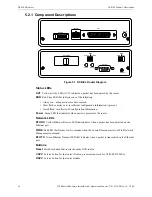
6.2.1 Component Descriptions
Figure 6.1 NCB-FL Router Diagram
Status LEDs
ACT
Yellow activity LED (ACT); indicates a packet has been passed by the router.
ERR
Red Error LED that indicates one of the following:
• Always on: a diagnostic error has occurred.
• Slow flash or always on: insufficient configuration information is present.
• Quick flash: insufficient IP configuration information.
Power
Green LED that indicates when power is present for the router.
Network LEDs
ETH RX
Yellow Ethernet Receive LED that indicates when a packet has been detected on the
Ethernet port.
WINK
Red LED that flashes for two seconds when the Control Neuron receives a Wink Network
Management command.
ETH TX
Green Ethernet Transmit LED that indicates when a packet is transmitted on the Ethernet
port.
Buttons
Reset
Hardware button that resets the entire NCB router.
CSVC
Service button for the router's Neuron processor (not used for NCB-EL/NCB-FL).
RSVC
Service button for the router module.
To NCB Module
AUI Port - Fiber
NCB-FL Fiber Adapter
Receive
Transmit
ERR
PWR
ACT
RESET
ASYNC
WINK
ETH TX
ETH RX
NETWORK
CSVC
RSVC
DC IN
AUI
10BASE-T
OPTION


