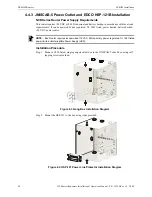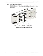
NCB-IM Installation
NCB-IM Routers
29
IFI Routers/Repeaters Installation & Operation Manual - P/N: 53388:Rev: A1 5/5/09
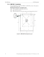
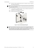
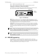
Step 3. Route power wiring in conduit through the bottom of cabinet and connect the wiring to the
line side (input) of the HSP-121.
Step 4. Connect the HSP-121’s EQUIP side (output) to single, grounded electrical outlet that will
be mounted in the single gang electrical box.
Step 5. Install the outlet into the single gang electrical box.
Step 6. Install the single gang electrical box’s plate.
Figure 4.5 Power Outlet Installation Diagram
NOTE:
Use only wire for power limited systems
.
Power limited wire runs use type FPLR, FPLP, FPL
or equivalent cabling per NEC 760.
NOTE:
Power-limited and non-power-limited circuits must remain separated in the cabinet
.
All
power-limited wiring must remain at least 0.25 inches from any non-power-limited circuit wiring
.
Run
all non-power-limited wiring along bottom of cabinet
.
All power-limited and non-power-limited circuit
wiring must enter and exit the cabinet through different knockouts and/or conduits.


