FX70 Supervisory Controller Installation Instructions
9
Option Card COM Port Assignments
For a list of supported COM port and slot assignments
for the option cards, see Table 6.
Installing an Option Card
For option-specific details, refer to the installation
instructions that accompany the particular option card.
The following procedure provides a basic set of steps.
1.
Remove power from the controller, including any
external battery.
2.
Remove the cover. See
3.
Remove the blanking plate for the option slot,
retaining the two screws. Retain the blanking plate
in case the option card must be removed later.
4.
Carefully insert the pins of the option card into the
socket headers of the option card slot.
Note:
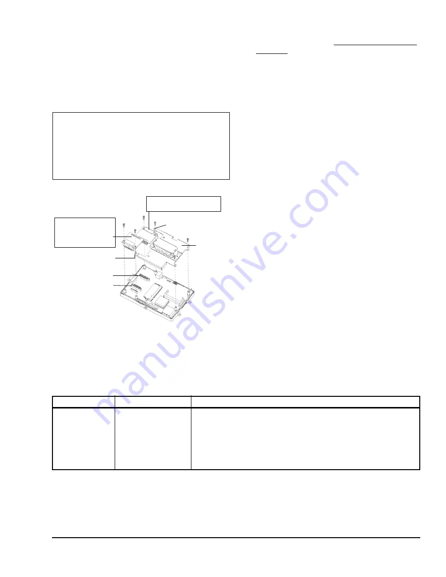
If installing in Slot 2, first carefully pry up the
shield tab that goes over the standoff. Option card
2 must be installed under the shield tab. See
Figure 7 for an exploded view.
The mounting holes on the option board should line
up with the standoffs on the base board. If they do
not, the connector is not properly aligned. Press
until the option card is completely seated.
5.
Place the custom end plate for the option card over
the connector(s) of the option card. With some
option cards, the card’s end plate is pre-fastened.
6.
With the mounting holes aligned with the standoffs,
place the two screws through the end plate, and
into the standoffs on the controller’s base board.
Using a screwdriver, hand tighten these screws.
7.
Replace the cover on the controller.
Remote I/O Modules
The FX70 has an integral 6-pin connector to support
remote I/O modules. The connector provides both
15 VDC power and RS-485 communications to
modules on that connected trunk, and is located on the
right side of the unit.
Each remote I/O module has a DIN-mount base, and
provides two 6-pin connectors that allow you to
daisy-chain multiple modules together into one
assembly. Table 2 lists the currently available modules.
MiniPCI Cards
The controller has one available MiniPCI slot (see
Figure 6).This slot supports a specific 802.11 wireless
(Wi-Fi) adapter option (no longer available).
Wiring
See Figure 6 to locate connectors and components on
the controller.
IMPORTANT:
Installing an option card in option
Slot 2 requires careful attention—you must carefully
pry up the shield tab to install the option card under
the tab. Do not install an option card in Slot 2 with
the card resting on top of the shield tab. Otherwise,
an electrical short or some other issue from
misaligned card header pins may result.
Figure 7: FX70 Option Card and Shield Removal
Shield Tab
Option
Slot 2
Option
Slot 1
Shield with
NiMH Battery
Assembly
Option card in Slot 2 must be
installed
under
the shield tab.
Shield Tab
Option card or blanking
plate in Slot 1 must be
removed before shield
can be removed.
F
IG
:f
x70
_opt
_c
rd_s
hl
d_r
em
v
Table 2: Remote I/O Modules Compatible with the FX70 Supervisory Controller
Model
Description
Notes
LP-FXRIO16-0
Remote I/O RS-485
Module
DIN-mountable RS-485
comm module that
provides 16 points I/O,
with I/O point types as
noted.
Provides the following I/O points:
8 - Universal Inputs (UIs).
4 - Digital Outputs (DOs), Single-Pole Single-Throw (SPST) relay type.
4 - Analog Outputs, 0–10 VDC type.
Up to 16 (maximum) LP-FXRIO16-0 accessory modules are supported.
Wiring is covered in a separate
document. Refer to the
LP-FXRIO16 Input/
Output Module Installation Instructions (Part No. 24-10564-41)
.


