RXF ROTARY SCREW COMPRESSOR UNITS
INSTALLATION
070.410-IOM (JAN 12)
Page 7
NOTE: Care must be taken when entering the unit to
ensure that the nitrogen charge is safely released.
Holding charge shipping gauges on
separator and external oil cooler are
rated for 30 PSIG and are for check-
ing the shipping charge only. They must be removed
before pressure testing the system and before charging
the system with refrigerant. Failure to remove these
gauges may result in catastrophic failure of the gauge and
uncontrolled release of refrigerant resulting in serious
injury or death.
All units must be kept in a clean, dry location to prevent
corrosion damage. Reasonable consideration must be given
to proper care for the solid-state components of the mi-
croprocessor.
Units which will be stored for more than two months must
have the nitrogen charge checked periodically. Contact
Johnson Controls-Frick for long term storage procedure.
COMPRESSOR OIL
DO NOT MIX OILS of different
brands, manufacturers, or types.
Mixing of oils may cause excessive
oil foaming, nuisance oil level cutouts, oil pressure loss,
gas or oil leakage and catastrophic compressor failure.
NOTE: The oil charge shipped with the unit is the best
suited lubricant for the conditions specified at the time
of purchase. If there is any doubt due to the refrigerant,
operating pressures, or temperatures; refer to Frick pub-
lication 160-802 SPC for guidance.
OIL CHARGE
The normal charging level is midway in the top sight
glass located midway along the oil separator shell.
Normal
operat ing level is between the top sight glass and bottom
sight glass. Oil charge quantities are as follows:
BASIC
ADDITIONAL FOR
RXF
CHARGE
OIL COOLER
MODEL
(gallon)
(gallon)
12 – 19
10
1
24 – 50
11
1
58, 68
25
3½
85, 101
36
3½
Add oil by attaching the end of a suitable pressure type
hose to the oil drain valve, located under the oil separator.
Using a pressure-type pump and the recommended Frick
®
oil, open the drain valve and pump oil into the separator.
NOTE: Evacuation of the oil separator will assist the flow
of oil into the unit. Also, fill slowly because oil will fill up
in the separator faster than it shows in the sight glass.
Oil distillers and similar equipment which trap oil must be
filled prior to unit operation to normal design outlet levels.
The same pump used to charge the unit may be used for
filling these auxiliary oil reservoirs.
The sight glass located near the bottom of the separator shell
at the discharge end should remain empty when the unit is
in operation. The presence of oil in this end of the vessel
during operation indicates liquid carryover or malfunc tion
of the oil return.
OIL HEATER
Standard units are equipped with 500 watt oil heaters, which
provide sufficient heat to maintain the oil tempera ture for
most indoor applications during shutdown cycles and to
permit safe start-up. RXF 12–50 use one heater while mod-
els 58–101 use two. Should additional heating capacity be
required because of an unusual environmental condition,
contact Johnson Controls-Frick. The heater is energized only
when the unit is not in operation.
Do not energize the heater when there
is no oil in the unit, otherwise the
heater will burn out. The oil heater
will be energized whenever 120 volt control power is applied
to the unit and the compressor is not running, unless the
16 amp circuit breaker in micro enclosure is turned off (or
15 amp fuse (1FU) in the Plus panel is removed).
OIL FILTER(S)
Use of filter elements other than
Frick may cause warranty claim to
be denied.
The oil filter(s) and coalescer filter element(s) shipped with
the unit are best suited to ensure proper filtration and op-
eration of the system.
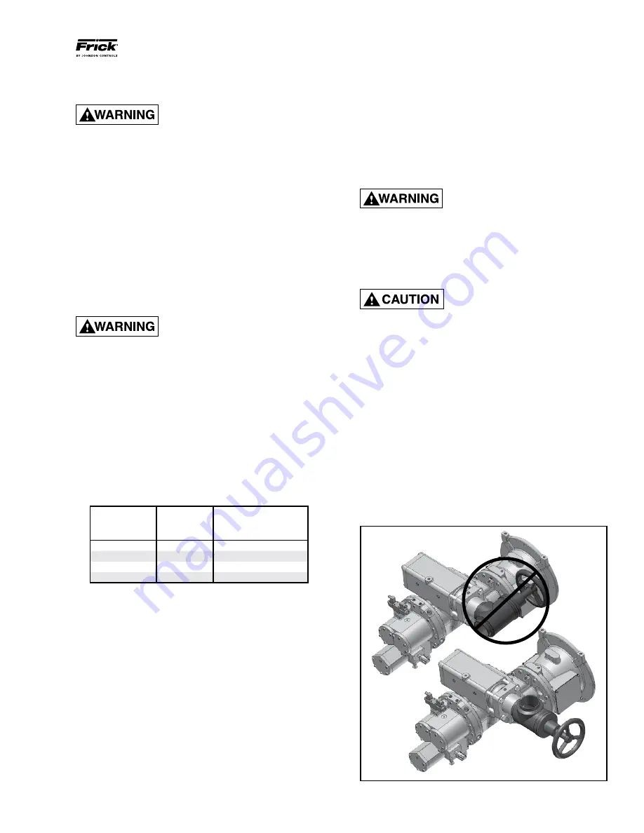
SUCTION ISOLATION VALVE MOUNTING
The suction isolation valve is shipped loose from the factory,
so it can be installed at various positions within the suction
line piping to the compressor.
DO NOT INSTALL
the valve at
the compressor suction with flow
against the cone/button
(see Figure 3 TOP). When the isolation valve is installed in
this position, uneven flow is generated across the suction
check valve which is mounted at the inlet to the compressor.
This uneven flow causes the disks in the check valve to strike
against the stop pin, and eventually damage the internals
of the check valve. If the isolation valve is mounted at the
compressor suction,
DO INSTALL
with flow
across the cone/
button
(see Figure 3 BOTTOM). Please design your system
piping accordingly.
INCORRECT!
CORRECT!
Figure 3 - Suction Isolation Valve Mounting


